Tools / Generators
Owner's Manual for Generac 1.5L Stationary Emergency Generator
Comprehensive owner's manual for the Generac 1.5L Stationary Emergency Generator. Includes installation, operation, maintenance, fuel system configuration, troubleshooting, and technical specifications.
Table of contents
Manual images
Click an image to enlargeQuick guide from the manual
This manual provides essential information for the safe operation and maintenance of the Generac 1.5L Stationary Emergency Generator. Installation must be performed by a qualified electrician or contractor. The unit is factory-configured for Natural Gas (NG); conversion to Liquid Propane (LP) requires specific mechanical and control panel reconfiguration. Always ensure the unit is properly ventilated and that exhaust gases are directed away from buildings.
Safety Rules
The generator produces lethal voltages and exhaust fumes. Observe all DANGER, WARNING, and CAUTION labels. Key safety measures include:
- Electrical Hazards: Never handle electrical devices while standing in water or with wet hands. Ensure all covers and guards are in place.
- Fire and Explosion: Keep a fire extinguisher nearby. Do not smoke near the unit. Ensure proper ventilation to prevent explosive gas buildup.
- Maintenance Safety: Always disconnect the negative battery cable before performing maintenance to prevent accidental startup.
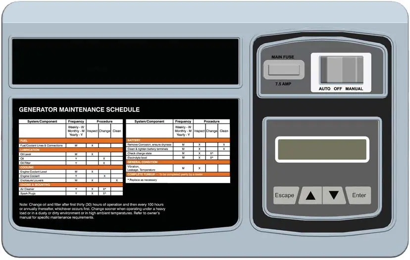
Control Panel and Operation
The control panel manages the generator's automatic and manual functions. The Auto/Off/Manual switch must be set to OFF and the fuse removed before servicing. The unit must be activated using the serial number and an activation code from the manufacturer's website before it will run automatically during a power outage.
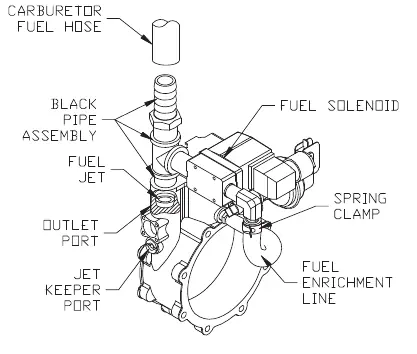
Fuel System
The generator is factory-configured for Natural Gas. To convert to LP, follow the mechanical conversion steps in the manual, which include swapping the fuel jet and reconfiguring the fuel type in the control panel. This conversion is password-protected to comply with EPA regulations.
Maintenance
Regular maintenance is critical for reliability. Key tasks include:
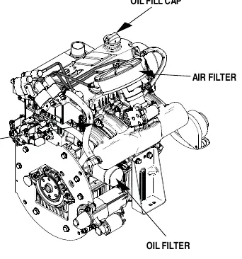
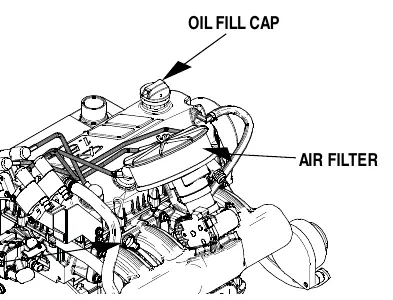
- Engine Oil: Check level monthly. Change oil and filter after the first 30 hours, then every 100 hours or annually.
- Cooling System: Keep intake/outlet openings clear of debris. Flush and refill coolant annually.
- Battery: Inspect posts and cables for corrosion. Maintain fluid levels in unsealed batteries using distilled water only.
- Air Filter: Inspect and replace as necessary.
Troubleshooting
If the engine fails to crank, check the 7.5A control panel fuse, battery cables, and battery charge. If the engine cranks but won't start, verify fuel supply and fuel solenoid operation. If the unit shuts down after starting, check oil levels, coolant levels, and protective switches.
Manufacturer information
Generac Power Systems, Inc.
Practical help
Common problems
Engine won't crank
Check if the 7.5A control panel fuse is blown, inspect battery cables for corrosion or looseness, check the starter, or replace the battery.
Engine cranks but won't start
Verify fuel supply is on, check the fuel solenoid, or clean/regap/replace spark plugs.
Engine starts then shuts down
Check engine oil level, inspect cooling system for leaks, or check for defective oil pressure/coolant temperature switches.
No AC output
Check if the main line circuit breaker is tripped or open, or if the thermal circuit breaker is open.
Before use
- Ensure installation was performed by a qualified professional.
- Verify the fuel type (Natural Gas or LP) matches the current configuration.
- Check engine oil level using the dipstick.
- Ensure the battery is connected and fully charged.
- Verify all safety guards and covers are securely in place.
- Ensure the area around the generator is clear of debris.
Specs in practice
- Rated Synchronous RPM
- 3600 RPM for 60Hz operation.
- Operating Fuel Pressure
- 5 in. - 14 in. Water Column.
- System Voltage
- 12 Volts DC.
- Recommended Battery
- Group 26, 525CCA.
Images and diagrams
- Exploded views are provided for the connection box, cooling system, mounting base, battery, enclosure, and exhaust system.
- Wiring diagrams detail connections for various single-phase and three-phase configurations.
Model compatibility
- Factory configured for Natural Gas (NG).
- Requires mechanical and control panel reconfiguration for Liquid Propane (LP) fuel.

Manual page author
David Miller
Documentation analyst
Organizes user manual content into clear summaries, with attention to model details, product context, and everyday usability.