Electronics / Speakers & Soundbars
Installation Guide for Genius GUARD Signal Lamp
A comprehensive installation and maintenance guide for the Genius GUARD signal lamp. Includes step-by-step mounting instructions, wiring diagrams, antenna setup for standard and LED versions, and bulb replacement procedures.
PDF source: italiano · summary: English
Quick answers from the manual
Quick answer
- The Genius GUARD is a signal lamp available in traditional and LED versions. It requires vertical mounting on a flat surface to maintain IP55 protection, though horizontal/upturned mounting is permitted in covered areas. p. 4, 5
Key actions
- Mounting the lamp p. 4, 5
- Replacing the bulb p. 4, 5
Maintenance and reset
- Replace the bulb by pressing the locking tab, turning the cover anti-clockwise, and swapping the bulb. p. 4, 5
Show 2 more answers Show less
Technical specifications
| Parameter | Value | Meaning | Pages |
|---|---|---|---|
| Power Supply | 230V~, 115V~, 24V, 12V | Voltage requirements vary by model. | p. 4, 5 |
| Protection Class | IP55 | Dust and water protection. | p. 4, 5 |
| Operating Temperature | -20°C to +55°C | Ambient temperature range. | p. 4, 5 |
Where to find it in the PDF
- Installation and Connections p. 4, 5
- Antenna Installation p. 4, 5
- Maintenance p. 4, 5
Table of contents
Manual images
Click an image to enlargeImportant Information
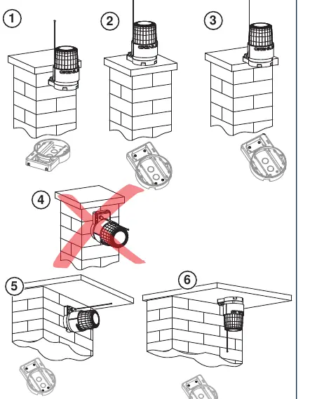
The Genius GUARD is a signal lamp designed for gate automation systems. It is available in traditional (bulb-based) and LED versions. To maintain the IP55 protection rating, the lamp must be installed on a flat surface, and the support must rest evenly. Horizontal or upturned mounting is only permitted in covered areas, such as buried boxes.
Description
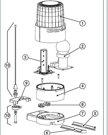
The unit consists of a cover, lamp-holder board (or LED board), cover base, slides, flashing lamp support, cable runner, and antenna support. The cover logo can be oriented in four positions (every 90°).
Installation and Connections
Before installing, ensure the location is visible from all directions, not obstructed by trees or signs, and is in the immediate vicinity of the gate. The unit must be fixed vertically, except in covered areas.
- Preparation: Clear the necessary fixing holes (Fig. 2) and choose the cable passage area (Fig. 3).
- Mounting: Fix the support using Ø5 wedges (Fig. 4).
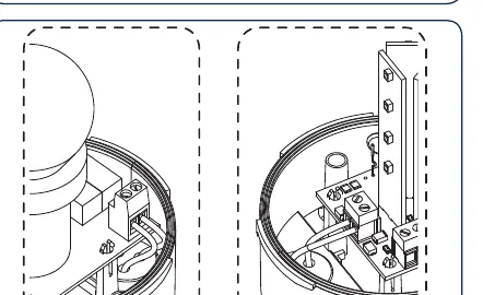
- Wiring: Route the power cable through the base and connect it to the board (Fig. 6).
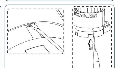
- Cover Assembly: Position the cover with the logo in the desired orientation. Turn anti-clockwise until it enters the housing, then clockwise until it locks. Ensure the locking tab on the base couples with the opening on the cover (Fig. 10).
- Slides: Install the two front slides (Fig. 11).
Antenna Installation
Standard GUARD
Open the pre-bored holes (Ø9), mount the antenna and accessories (Fig. 12), and route the antenna cable separately from the power cable.
LED GUARD
The LED version has a built-in antenna. To connect it: drill a 12.5mm hole in the cover support (Fig. 13), install an M12x1.5 (or PG7) cable runner, and connect the RG58 coaxial cable (not supplied) to the dedicated terminals.
Maintenance
To replace the light bulb: press the locking tab (Fig. 14), turn the cover anti-clockwise to remove it, replace the bulb with one of the same specifications, and refit the cover.
Manufacturer information
Genius
Practical help
Common problems
Antenna support cannot be removed
The antenna support cannot be removed once the cover is installed.
Horizontal or upturned mounting
This is only allowed in covered areas, such as buried boxes.
Loss of IP55 protection
Ensure the lamp is installed on a flat surface and the support rests evenly.
Before use
- Verify the power supply matches the model (230V, 115V, 24V, or 12V).
- Ensure the mounting surface is flat.
- Check that the lamp is visible from all directions.
- Ensure the lamp is not obstructed by trees, signs, or other objects.
- Confirm the unit is mounted vertically (unless in a covered area).
Show more Show less
Specs in practice
- Power Supply
- Ensure the voltage matches your specific model (230V~, 115V~, 24V, or 12V).
Images and diagrams
- Fig 1: Exploded view of all components.
- Fig 2: Allowed and prohibited mounting positions.
- Fig 3: Cable passage zones.
- Fig 14: Bulb replacement mechanism.
Model compatibility
- Standard models use E27 or E14/BA15S bulbs.
- LED models feature a built-in antenna.
- Antenna connection requires RG58 coaxial cable (not supplied).

Manual page author
Emily Carter
User documentation editor