Documents / Warranty Safety
Gowin 10G Serial Ethernet IP User Guide
Comprehensive user guide for implementing and configuring the Gowin 10G Serial Ethernet IP, covering functional descriptions, port definitions, and reference designs.
Table of contents
Manual images
Jump to the sectionProduct Overview
The Gowin 10G Serial Ethernet IP is designed to implement the functions described in the IEEE 802.3 standard Clause 49 for 10GBASE-R. It provides the necessary Physical Medium Attachment (PMA) and Physical Coding Sublayer (PCS) functions. The IP offers users an XGMII (10-Gigabit Media Independent Interface) compliant with IEEE 802.3 Clause 46, making it suitable for high-speed communication applications.

Key Features
- Supports IEEE 802.3 Clause 49 and 10GBASE-R protocols.
- Operates at a line rate of 10.3125Gbps.
- Includes serial data scrambling and descrambling.
- Provides a user-side XGMII interface.
- Supports RX clock elastic buffer for data synchronization.
- Specific models (GW5AT-138/75) include additional features like 64/66B decoding error block statistics and BER monitoring.
Functional Description
The IP structure integrates SerDes and PCS modules. The SerDes hardcore acts as the PMA, while the PCS implements the 10GBASE-R protocol. Users can interface this IP with a 10G Ethernet MAC or design a custom MAC to connect to the XGMII. The system requires precise clock management, with recommended frequencies of 156.25 MHz for the XGMII and internal operations. Proper clock connection, often involving PLLs for non-156.25 MHz reference clocks, is critical for stable operation.
Analog Front End (AFE)
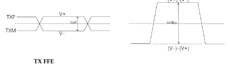
The AFE allows users to ensure signal integrity by configuring analog parameters. Users can adjust the transmit differential swing (180mV to 900mV) and utilize Feed-Forward Equalization (FFE). FFE can be set to Auto mode for automatic adjustment or Manual mode, where users can configure 3-tap coefficients (Cm, C0, C1) to optimize pre-emphasis. Receive signal thresholds can also be configured via the SD Threshold setting to manage valid data detection and Electrical Idle states.
Configuration and Integration
The IP is configured using the Gowin IP Core Generator tool within the IDE. Users can select the protocol, configure PHY settings such as channel selection, loopback modes, and reference clock sources, and generate the necessary Verilog files. The interface provides a clear path for setting up the SerDes and 10G Ethernet parameters, ensuring seamless integration into FPGA projects.
Manufacturer information
GOWIN Semiconductor
Practical help
Common problems
Invalid data detection
Adjust the SD Threshold parameter to ensure the received differential signal is correctly identified above the noise floor.
Clock synchronization issues
Ensure the reference clock is correctly connected. If using a non-156.25 MHz clock, use a PLL to generate the required 156.25 MHz input.
Before use
- Verify the target FPGA device supports the 10G Serial Ethernet IP.
- Ensure Gowin Software V1.9.9 or higher is installed.
- Confirm the reference clock source and frequency are compatible with the design.
- Check if the specific device (e.g., GW5AT-138/75) supports the required features like BER monitoring.
- Prepare the XGMII interface connections for the MAC layer.
Specs in practice
- Differential Swing
- The peak-to-peak voltage of the differential TX signal, configurable from 180mV to 900mV.
- SD Threshold
- Signal Detect threshold; determines the voltage level above which the receiver considers data valid.
Images and diagrams
- Figure 3-1: Shows the high-level block diagram including User Logic, MAC, PCS, and SerDes.
- Figure 3-2/3-3: Illustrates recommended clock connections for 156.25MHz and 125MHz reference clocks.
- Figure 3-6: Defines the differential signal swing (Vdiffpp) for the transmitter.
- Figure 7-1: Displays the hardware platform setup using a development board and SFP+ module.
Model compatibility
- Supports GW5AT series FPGAs.
- Requires Gowin Software V1.9.9 or newer.
- Some features like BER monitoring are exclusive to GW5AT-138/75 devices.

Manual page author
David Miller
Documentation analyst
Organizes user manual content into clear summaries, with attention to model details, product context, and everyday usability.