Baby / Swings & Bouncers
Repair Manual for Graco ProConnect Endurance Displacement Pump
Comprehensive repair and service manual for the Graco ProConnect Endurance Displacement Pump. Includes detailed instructions for pressure relief, pump removal, disassembly, assembly, installation, and parts lists for various models.
Quick answers from the manual
Quick answer
- This manual provides repair instructions for the Graco ProConnect Endurance Displacement Pump, including safety warnings, pressure relief procedures, disassembly, assembly, and parts lists. p. 1, 2
Key actions
- Perform Pressure Relief Procedure p. 5, 6, 7
- Tighten packing nut p. 16
Problems and fixes
Pump leaking
Perform Pressure Relief Procedure and tighten packing nut.
p. 16Maintenance and reset
- Tighten packing nut for leakage p. 16
Technical specifications
| Parameter | Value | Meaning | Pages |
|---|---|---|---|
| Maximum fluid working pressure | 3300 psi | Maximum operating pressure | p. 22 |
Where to find it in the PDF
- Pressure Relief Procedure p. 5, 6, 7
- Pump Removal p. 8
- Repair (Disassemble/Assemble) p. 9, 10, 11, 12
- Pump Installation p. 17
- Parts Lists p. 18, 19, 20, 21
Table of contents
Manual images
Click an image to enlargeImportant Safety Information
This manual contains critical safety instructions for the repair and maintenance of the Graco ProConnect Endurance Displacement Pump. Failure to follow these instructions can result in serious injury or death. Key hazards include fire and explosion, skin injection, and pressurized aluminum parts. Always wear appropriate personal protective equipment, including eye and hearing protection, and respirators as recommended by fluid manufacturers.
Pressure Relief Procedure
This equipment remains pressurized until manually relieved. You must perform the pressure relief procedure whenever you stop spraying, before cleaning, checking, or servicing the equipment.
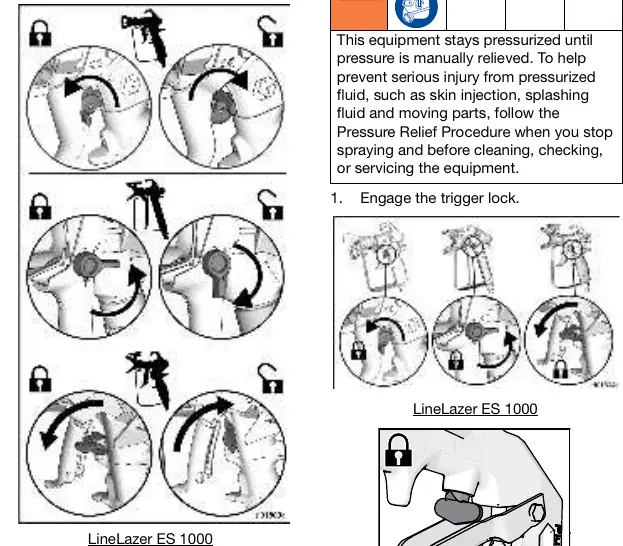
- Engage the trigger lock.
- Turn the ON/OFF switch to the OFF position and wait 7 seconds for power to dissipate.
- Unplug the power cord or shut off the engine. For LineLazer ES 1000, disconnect the battery.
- Engage the trigger lock.
- Remove the tip guard.
- Turn the pressure control to the lowest setting and disengage the trigger lock.
- Hold a metal part of the gun firmly to a grounded metal pail and trigger the gun to relieve pressure.
- Engage the trigger lock.
- Open any fluid drain valves in the system and leave them open until ready to spray again.
Pump Removal
To remove the pump for service:
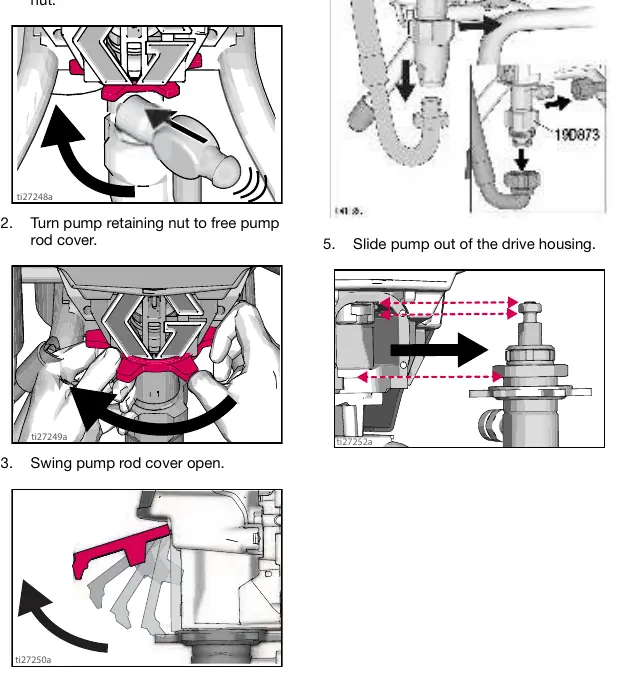
- Use a hammer to loosen the pump retaining nut.
- Turn the nut to free the pump rod cover and swing it open.
- Disconnect the outlet and suction hoses.
- Slide the pump out of the drive housing.
Repair and Maintenance
The manual provides detailed steps for disassembling and assembling the pump, including:
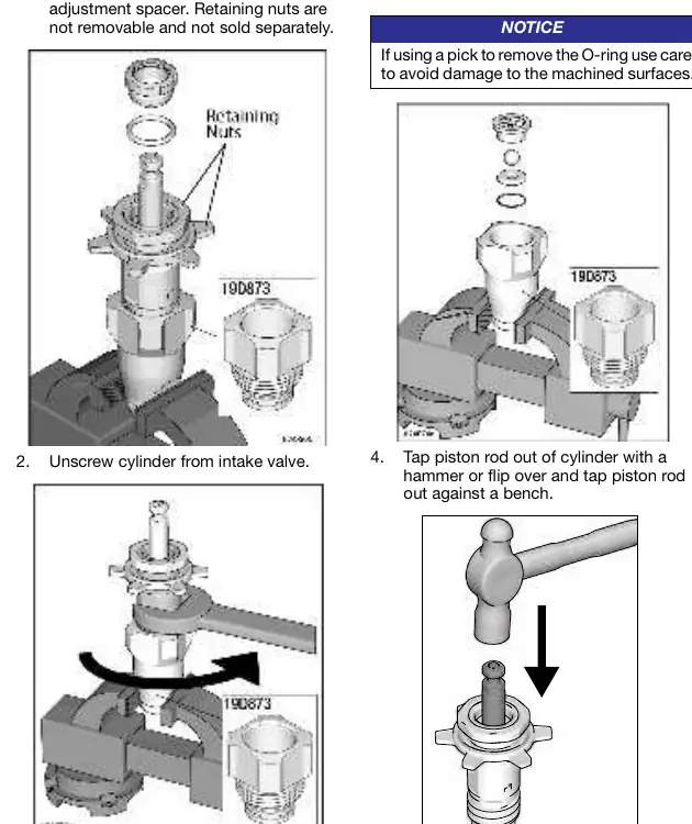
- Disassembly: Removing the packing nut, throat adjustment spacer, cylinder, intake valve, and piston rod.
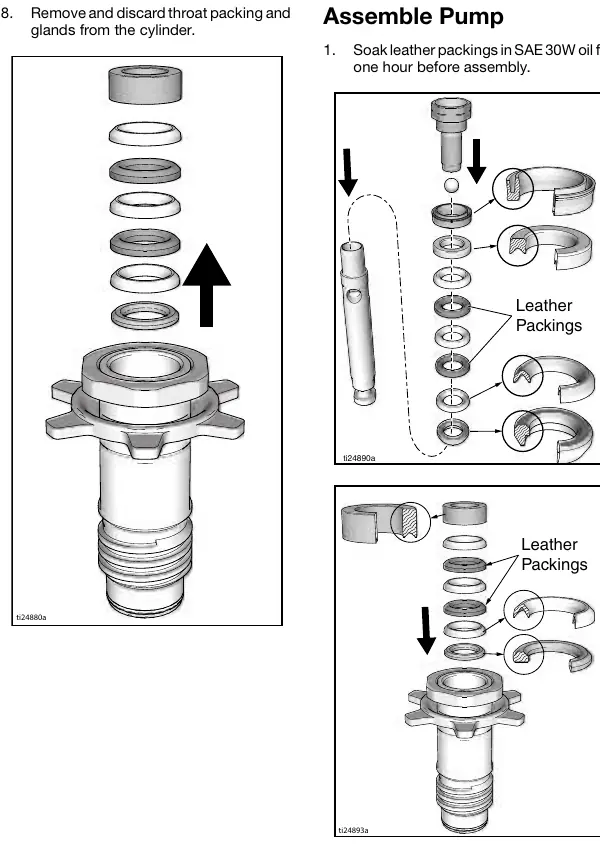
- Assembly: Soaking leather packings in SAE 30W oil for one hour before assembly. Installing balls, packings, and o-rings according to the specific model requirements.
- Throat Packing Adjustment: If leakage occurs, perform the pressure relief procedure and tighten the packing nut until leakage stops.
Pump Installation
To install the pump:
- Connect the outlet hose to the pump.
- Move the pump displacement rod until it slides into the connecting rod.
- Slide the pump into the drive housing.
- Close the pump rod cover, ensuring it is flush against the housing.
- Tighten the pump retaining nut by hand, then use a hammer to turn it an additional 1/8 to 1/6 turn (45° to 60°).
- Install the suction hose.
Technical Specifications
The pump is rated for a maximum fluid working pressure of 3300 psi (228 bar, 22.8 MPa). Fluid inlet size is 1.0 in. diameter, and fluid outlet size is 1/4 in. Wetted materials include stainless steel, PTFE, leather, nylon, zinc-plated and nickel-plated carbon steel, tungsten carbide, chrome plating, UHMWPE, acetal, and polyethylene.
Manufacturer information
Graco Inc.
Practical help
Common problems
Pump leaking
Perform the Pressure Relief Procedure, then tighten the packing nut down until leakage stops or lessens.
Nozzle tip clogs
Perform the Pressure Relief Procedure before removing the nozzle tip to clean.
Before use
- Ensure all containers and collection systems are grounded.
- Verify the trigger lock is functioning properly.
- Check hoses and parts for signs of damage.
- Wear appropriate protective equipment (eye, hearing, respirator, gloves).
- Verify all connections are secure.
Specs in practice
- Maximum fluid working pressure
- 3300 psi (228 bar, 22.8 MPa). Do not exceed this pressure.
- Fluid inlet size
- 1.0 in. diameter.
- Fluid outlet size
- 1/4 in.
Images and diagrams
- Exploded views of pump components are provided for models 17C487-19D873 and 19Y298-2002382.
- Pressure relief procedure diagrams illustrate the trigger lock and drain valve operation.
Model compatibility
- Use only genuine Graco replacement parts.
- Do not use halogenated hydrocarbon solvents (e.g., 1,1,1-trichloroethane, methylene chloride) or chlorine bleach as they react with aluminum.

Manual page author
David Miller
Documentation analyst
Organizes user manual content into clear summaries, with attention to model details, product context, and everyday usability.