Industrial / Pumps & Motors
User Manual for Marco 1E483115 Self-Priming Electric Pump
Quick guide for the Marco 1E483115 self-priming electric pump. Includes installation instructions, wiring, troubleshooting, LED status indicators, and technical specifications.
Quick answers from the manual
Quick answer
- The Marco 1E483115 is a self-priming electric pump for transferring liquids. It features an electronic pressure sensor and is suitable for washing operations with saltwater and freshwater. p. 1, 6
Key actions
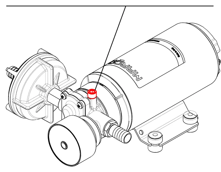
- Activate air vent valve during priming p. 2
- Resetting the pump p. 3, 4
First start
- Open air vent valve, start pump, close valve once operating. p. 2
Problems and fixes
Pump won't prime
Check height, air leaks, filter, or dry run.
p. 9Maintenance and reset
- Clean inlet filter and check chamber monthly. p. 10
Technical specifications
| Parameter | Value | Meaning | Pages |
|---|---|---|---|
| Voltage | 12/24 V | Operating voltage | p. 6 |
| Flow Rate | 18 l/min | Maximum flow rate | p. 6 |
Where to find it in the PDF
- Installation p. 7, 8
- Exploded View p. 11
Table of contents
Manual images
Click an image to enlargeQuick Start and Important Information
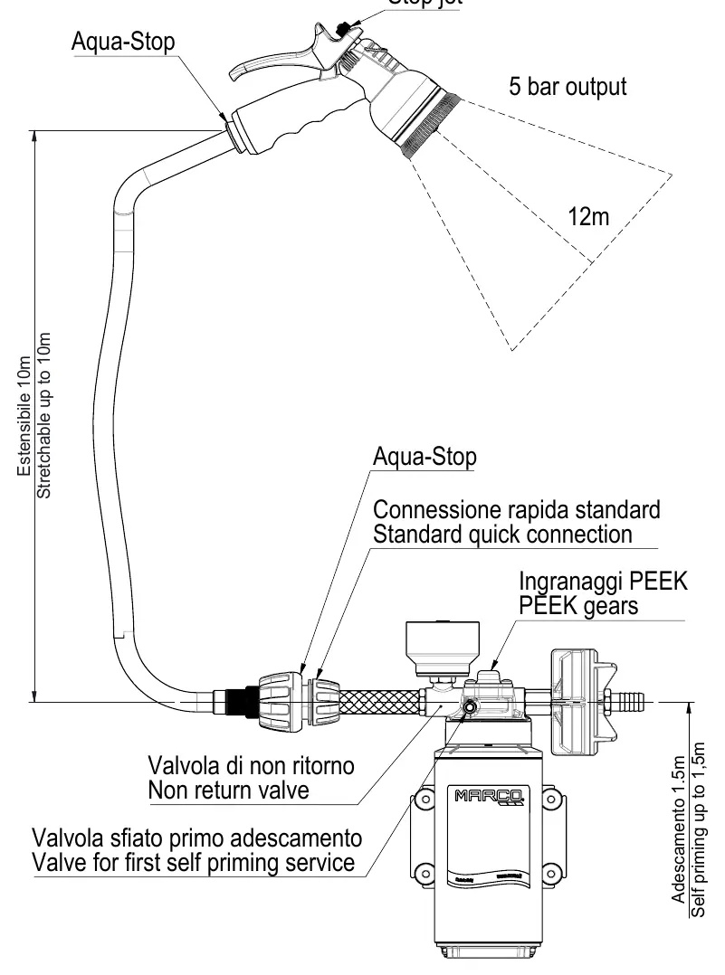
The Marco 1E483115 is a self-priming electric pump designed for transferring various liquids, including saltwater and freshwater. It features an electronic pressure sensor to control pump speed, reduce noise, and optimize consumption. Before starting, ensure the air vent valve is slightly opened to facilitate priming, then close it once the pump is operating.
Installation
The pump can be mounted in any position. Ensure the inlet and outlet ports are clean and free of packaging material. Use suitable screws to fix the pump. For electrical connections, connect the positive pole (+) of the battery to the red wire and the negative pole (-) to the black wire. Use adequate terminal blocks and ensure a tight fit. An expansion tank of at least 0.5 liters is recommended if using short, rigid pipes or solenoid valves to prevent water hammer effects.
Operation and LED Indicators
The electronic pressure sensor uses two LEDs (blue and multicolored) to indicate status:
- Blue LED: Indicates liquid presence. Flashes during priming mode.
- Solid Yellow: Pump is trying to reach target pressure.
- Solid Green: Target pressure reached, flow is constant.
- Flashing Green: Stand-by mode, motor off.
- Solid/Slowly Flashing Red: Short circuit or blockage.
- Fast Flashing Red: Overload (viscous liquids or overheating).
If the pump stops, it may need to be reset by rebooting the circuit or pressing the Reset button on the control panel, if present.
Maintenance
Regular maintenance is essential for longevity:
- Frequently clean the inlet filter.
- Check the pump chamber monthly for foreign matter.
- Verify electrical wiring condition monthly.
- If the pump will be unused for 30+ days, run fresh water through it and loosen the front plate screws.
Troubleshooting
If the pump fails to prime, check for excessive height above the fluid level, air leaks in the suction pipe, or obstructions. Ensure the fuse is intact and the battery voltage is sufficient. Avoid running the pump dry for extended periods, as this can damage the internal components.
Practical help
Common problems
Pump will not prime
Check for excessive height, air leaks in suction pipe, clogged filter, or dry run conditions.
Pump stopped / LED red
Check for short circuits, blockages, or overloads. Reset by rebooting the circuit or pressing the Reset button.
Pump runs dry
Avoid running dry for more than a few minutes to prevent damage not covered by warranty.
Before use
- Inspect for transport damage.
- Clean inlet and outlet ports.
- Verify power supply voltage (12/24V).
- Install inlet filter (mesh ASTM no. 35).
- Ensure correct wire section for power supply.
- Mount anti-vibration rubber fittings.
Images and diagrams
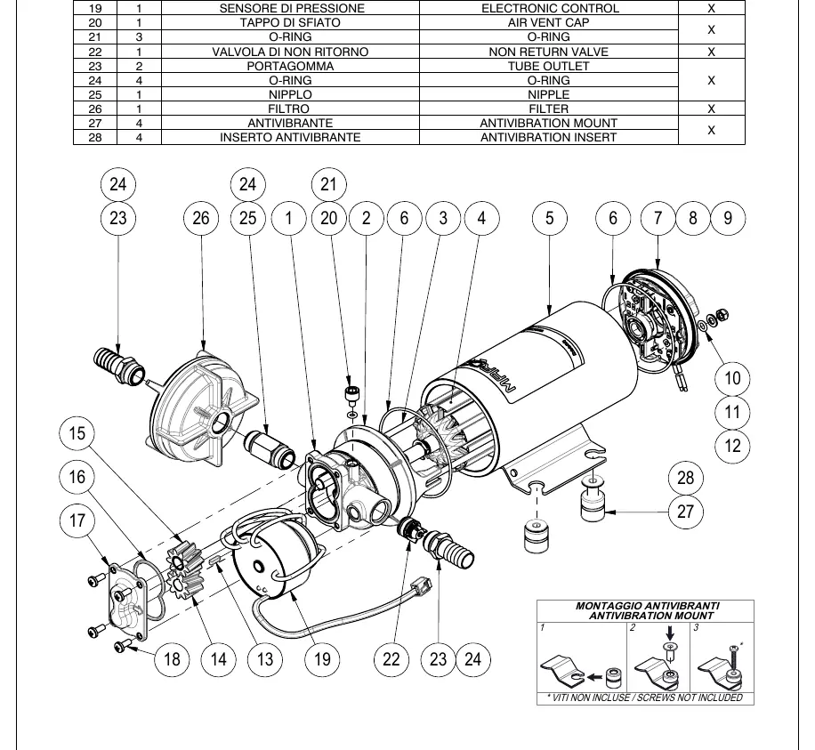
- Exploded view shows all internal components and assembly order.
- Kit diagram illustrates the connection of the spray gun, hose, and pump.
Model compatibility
- Not suitable for petrol, solvents, or corrosive chemicals.
- Max fluid temperature: 85°C.
- ISO 8846 Compliant Device.

Manual page author
David Miller
Documentation analyst
Organizes user manual content into clear summaries, with attention to model details, product context, and everyday usability.