Power / Energy Storage Systems
User Manual for Growatt ARK 2.5L-A1 Battery System
Comprehensive user guide for the Growatt ARK 2.5L-A1 Battery System. Includes installation instructions, electrical connection diagrams, power-on procedures, maintenance guidelines, and troubleshooting steps.
Quick answers from the manual
Quick answer
- The Growatt ARK 2.5L-A1 is a modular lithium iron phosphate battery system. It is installed by mounting the battery modules (wall or floor) and connecting them to a PCS via power and CAN communication cables. Power is managed via the power button on the front panel. p. 3, 7, 9, 10
Key actions
- Powering on the battery p. 10
- Installing the battery p. 7, 8
First start
- Connect battery to PCS, close breaker, and press power button for 3-8 seconds. p. 10
Problems and fixes
ALM light flickers
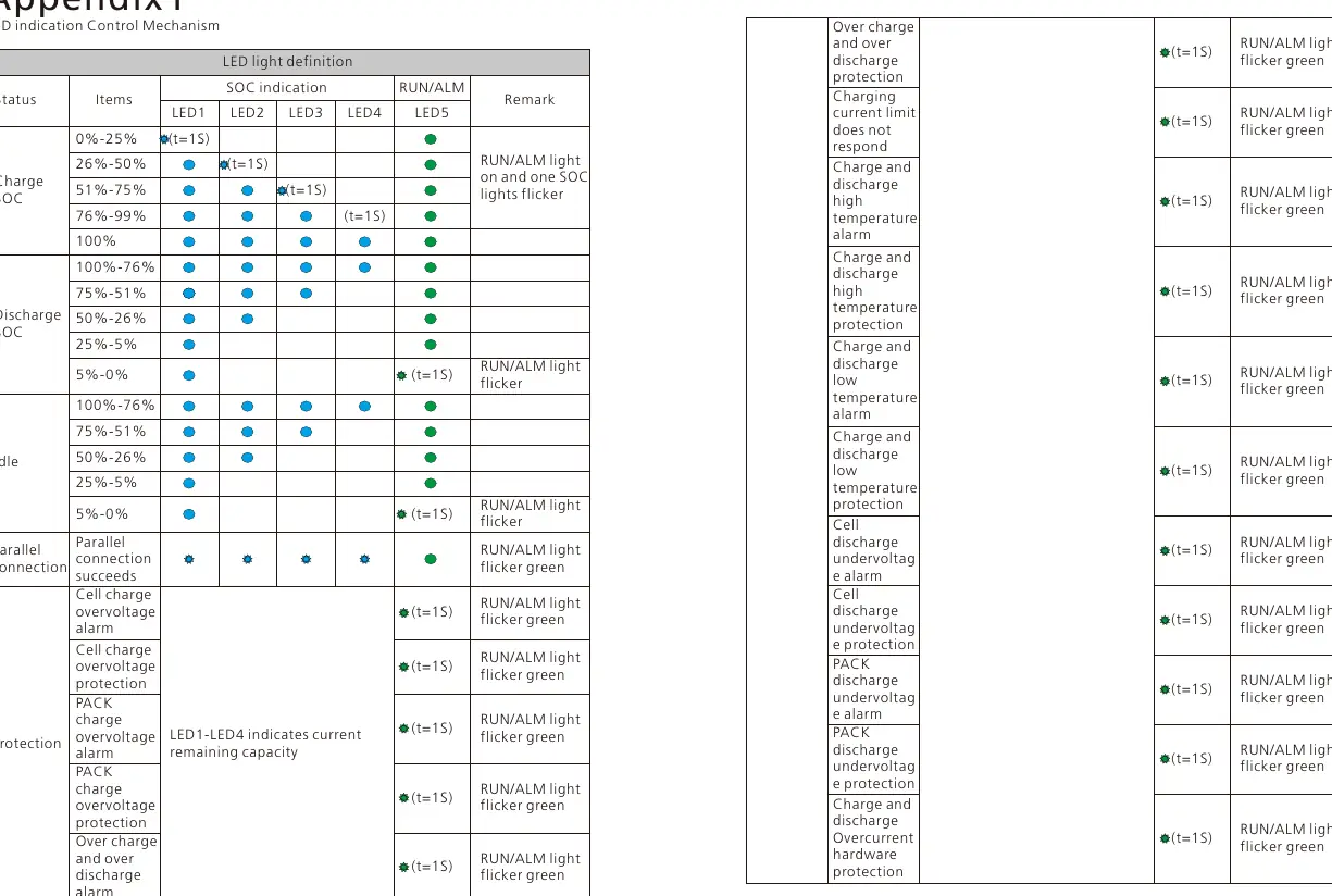
Check for communication failure, under/over voltage protection, or temperature alarms.
p. 10, 11, 12Maintenance and reset
- To maintain or replace, power off the system, disconnect lines, and follow the removal procedure. p. 10
Technical specifications
| Parameter | Value | Meaning | Pages |
|---|---|---|---|
| Nominal Voltage | 51.2V | Standard operating voltage | p. 11 |
| Capacity | 50Ah / 2.56kWh | Energy storage capacity | p. 11 |
Where to find it in the PDF
- Product Overview p. 3
- Installation p. 7, 8, 9
- Technical Specifications p. 11
Table of contents
Manual images
Click an image to enlargeQuick Guide
The Growatt ARK 2.5L-A1 is a modular energy storage battery system. This manual covers the installation, operation, and maintenance of the system. Key safety requirements include ensuring the installation environment is between -10°C and 50°C, using insulated tools, and ensuring proper grounding. The system supports parallel connection of 2 to 10 packs.
Product Overview
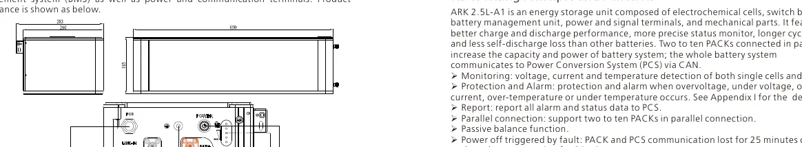
The ARK 2.5L-A1 consists of 50Ah cells forming a 51.2V module. It features a Battery Management System (BMS) for monitoring voltage, current, and temperature. The front panel includes communication interfaces (PCS, LINK-IN, LINK-OUT), power terminals, a USB interface for upgrades, and a power button.
Safety Precautions
Important: Do not disassemble the battery, touch terminals with wet hands, or expose the unit to temperatures above 50°C. Ensure the system is installed in a dry, well-ventilated area away from direct sunlight and heat sources. In case of fire, evacuate immediately; do not attempt to extinguish the battery fire.
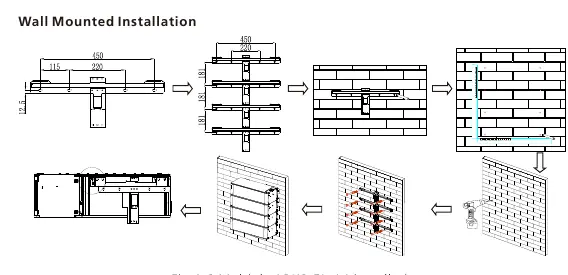
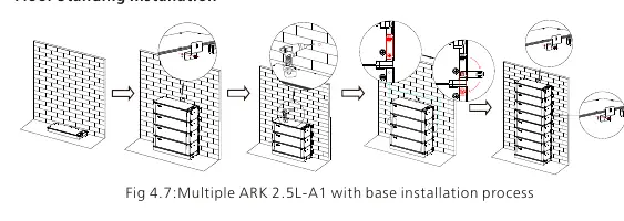
Installation
The system can be installed wall-mounted or floor-standing. Ensure the wall can support at least 150kg. Use a drill, screwdriver, wrench, pencil, tape measure, and multimeter for installation. Follow the specific steps for wall hangers or the base installation provided in the manual. Always ensure the battery is powered off before starting installation.
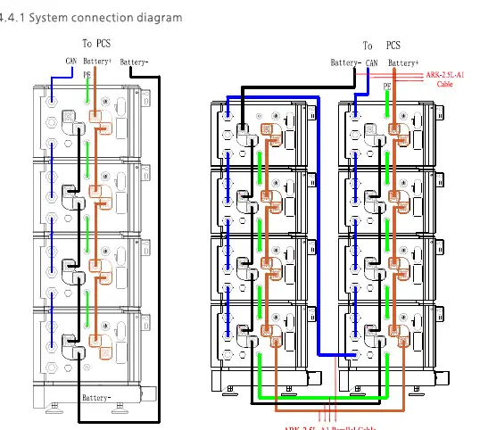
Electrical Connection
Connect the positive (red) and negative (black) power lines to the respective terminals. Connect the CAN communication line between the PCS and the battery. For parallel systems, use the provided parallel cables to link communication ports between modules. Ensure the ground wire is installed for system security.
Power On and Off
To power on, connect the battery to the PCS, close the breaker, and press the power button for 3-8 seconds. The system is successfully powered on if the RUN/ALM and SOC lights turn on. To power off, press the power button once.
Maintenance and Troubleshooting
Regular maintenance involves checking connections and ensuring the system is clean. If the ALM light flickers or stays on, refer to the troubleshooting table in the manual. Common issues include communication failures or voltage protection triggers. If a module needs replacement, power off the system, disconnect all lines, and follow the removal procedure.
Technical Specifications
The ARK 2.5L-A1 has a nominal capacity of 2.56kWh (50Ah) and a nominal voltage of 51.2V. It operates between -10°C and 50°C and has an IP65 ingress protection rating. It supports parallel connection of up to 10 units.
Manufacturer information
Growatt New Energy
Practical help
Common problems
ALM light flickers (External CAN Communication failure)
Check if the PCS and battery communication terminal are well connected. If the issue persists, contact the installer.
Discharge under voltage protection
Stop discharging immediately and arrange for a recharge.
Charge over voltage protection
Stop charging. The system will return to normal status once the voltage drops below the threshold.
Before use
- Ensure the installation wall can support at least 150kg.
- Verify that the battery is powered off before installation.
- Wear insulated gloves, safety goggles, and safety shoes.
- Check that all parts are present according to the package list.
- Ensure the ambient temperature is between -10°C and 50°C.
Specs in practice
- Nominal Voltage
- 51.2V, the standard operating voltage of the battery module.
- Nominal Capacity
- 50Ah / 2.56kWh, the total energy storage capacity of one module.
Images and diagrams
- Fig 1.1: Shows the connector face, including communication ports, power terminals, and the power button.
- Fig 4.6: Illustrates the wall-mounted installation process for multiple battery packs.
- Fig 4.9: Displays the system connection diagram for parallel battery stacks.
Model compatibility
- Supports parallel connection of 2 to 10 ARK 2.5L-A1 packs.
- Requires PCS (Power Conversion System) for operation.
- Communication via CAN/RS485.

Manual page author
Michael Turner
Technical manual editor
Reviews PDF manuals for structure, safety notes, and practical product details so readers can find the right information quickly.