Power / Solar Inverters
Installation and Operation Manual for Growatt MID 17KTL3-X Inverter
A comprehensive installation and operation guide for the Growatt MID 17KTL3-X series PV inverter. This manual covers safety instructions, mounting requirements, electrical wiring (AC/DC), system debugging, OLED display operation...
Quick answers from the manual
Quick answer
- The Growatt MID 17KTL3-X is a grid-connected PV inverter. Installation must be performed by a qualified electrician. Ensure proper clearance (300mm above, 500mm sides/under) and follow all safety guidelines, including waiting 5 minutes after power-off before maintenance. p. 4, 7, 8, 15
Key actions
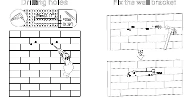
- Mounting the inverter p. 7, 8
- Wiring AC/DC p. 9, 10, 11
- Cleaning the fan p. 15, 16
First start
- Close DC switch (if voltage > 250V), then close AC circuit breaker. p. 13, 15
Problems and fixes
Warning 300 (No Utility)
Confirm grid is present.
p. 17
Error 202 (DC input voltage high)
Disconnect DC switch and check voltage.
p. 18Maintenance and reset
- Clean fan or heat sink if clogged; replace fan if damaged. p. 15, 16
Technical specifications
| Parameter | Value | Meaning | Pages |
|---|---|---|---|
| Max. DC Voltage | 1100V | Maximum input voltage | p. 21 |
| Weight | 23kg | Unit weight | p. 6, 20 |
Where to find it in the PDF
- Installation p. 7, 8, 9
- Troubleshooting p. 16, 17, 18, 19
Table of contents
Manual images
Click an image to enlargeQuick Guide from the Manual
This manual provides essential instructions for the installation, commissioning, and maintenance of the Growatt MID 17KTL3-X series photovoltaic inverters. Important: Installation must be performed by a qualified electrician. Always wait at least 5 minutes after powering off the device before performing any maintenance to ensure the machine is fully discharged.
Safety Instructions
- Ensure the DC switch is in the OFF state before any wiring.
- Do not touch live parts; high voltage is present.
- Ensure the inverter is grounded properly.
- Use opaque materials to cover PV modules during installation to prevent high voltage hazards.
- The outer casing can become hot; handle with care.
Installation
The inverter is IP65 rated and suitable for indoor or outdoor use. Ensure the mounting wall is sturdy and can support the weight of the unit.
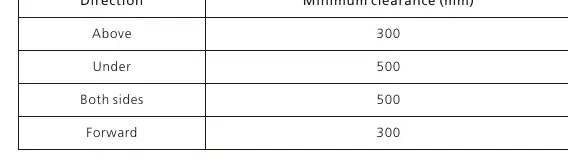
Clearance Requirements
- Above: 300mm
- Under: 500mm
- Sides: 500mm
- Forward: 300mm
The inverter should be mounted in an eye-view orientation and not exposed to direct sunlight to prevent overheating.
Wiring
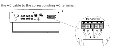
AC Side Wiring
Each inverter must be independently installed with an AC circuit breaker. Do not use single-core wire at the output. Ensure the cable connector is securely tightened to prevent moisture and dust ingress.
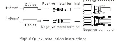
DC Side Wiring
Ensure the DC input polarity is correct. The maximum open-circuit voltage of each string must not exceed 1100Vdc. Ensure the PV string is not grounded if the output is directly connected to the grid.
Operation
The inverter features an OLED display and touch buttons. Use the touch interface to switch display pages, confirm settings, or navigate menus. The display automatically turns off after 5 minutes of inactivity.
Maintenance
The inverter is equipped with a cooling fan. If the fan is clogged or dusty, clean it with a brush or damp cloth. Do not use a gas pump to clean the fan. Ensure the device is powered off and disconnected from AC/DC sources for at least 10 minutes before maintenance.
Troubleshooting
If a fault occurs, an error message will appear on the OLED screen. Refer to the troubleshooting section for specific warning and error codes. Common actions include checking grid voltage, verifying wiring, or restarting the inverter.
Manufacturer information
Growatt New Energy
Practical help
Common problems
Inverter not starting
Ensure DC input voltage is >250V and the AC circuit breaker is closed.
Fan error (Warning 400)
Check fan connection, clean the fan/heat sink, or replace the fan if damaged.
Communication fault
Check communication wire connections and ensure the cable is not damaged.
DC input voltage high (Error 202)
Immediately disconnect the DC switch and verify the input voltage.
Before use
- Verify the wall can support the inverter's weight (23kg).
- Ensure proper clearance (300mm above, 500mm sides/under).
- Check that the installation location is not in a living area.
- Ensure the DC switch is OFF before starting wiring.
- Verify PV module polarity before connecting to DC terminals.
Specs in practice
- Max. DC Voltage
- The maximum input voltage the inverter can handle (1100V).
- Protection Level
- IP65, indicating the device is dust-tight and protected against water jets.
- Operating Temperature
- The ambient temperature range for operation is -25°C to +60°C.
Images and diagrams
- Figure 5.1: Shows the required clearance distances for the inverter.
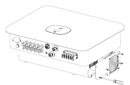
- Figure 6.3: Illustrates the correct AC terminal wiring.
- Figure 6.6: Shows the DC terminal connection instructions.
- Figure 12.1: Demonstrates how to remove the fan for cleaning or replacement.
Model compatibility
- Compatible with RS485, Wifi, GPRS, and 4G communication modules.
- Requires professional installation by a qualified electrician.

Manual page author
Emily Carter
User documentation editor
Prepares concise manual descriptions and highlights the most useful setup, operation, and maintenance information for readers.