Power / Energy Storage Systems
Growatt ARK 2.5L-A1 Lithium Battery Module Installation Guide
Comprehensive installation and operation guide for the Growatt ARK 2.5L-A1 lithium battery module. Includes mounting instructions, wiring diagrams, terminal connections, and system startup procedures.
Quick answers from the manual
Quick answer
- The Growatt ARK 2.5L-A1 is a lithium battery module. To install, mount it on a wall (max 4 units, >150kg capacity) or floor using the base. Connect the PCS and battery modules using the provided parallel cables and a circuit breaker (>80V, >125A). Power on by holding the button for ≥2 seconds. p. 1, 2
Key actions
- Power on the system p. 2
- Shut down the system p. 2
- Install wall-mounted units p. 1
First start
- Press the power button on any module for ≥2 seconds to start the system. p. 2
Maintenance and reset
- Shut down the system by pressing the power button once. p. 2
Technical specifications
| Parameter | Value | Meaning | Pages |
|---|---|---|---|
| Circuit Breaker | >80V, >125A | Recommended rating for the switch connecting PCS to ARK-2.5L-A1. | p. 2 |
Where to find it in the PDF
- Installation and Packing List p. 1
- Wiring and Operation p. 2
Table of contents
Manual images
Click an image to enlargeQuick guide from the manual
The Growatt ARK 2.5L-A1 is a lithium battery module designed for energy storage systems. This guide covers the installation, wiring, and operation of the unit. Ensure the installation environment is between -10°C and +50°C with a relative humidity of 5% to 95%. For wall-mounted installations, ensure the wall can support at least 150kg and do not exceed four stacked units.
Installation preparation
Before beginning, verify all components are present in the packing list:
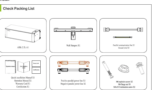
- ARK-2.5L-A1 battery module
- Wall hangers
- Parallel communication line and ground wire
- Power cables (positive and negative)
- Mounting hardware (screws, bolts, nuts)
Installation methods
The system supports both floor and wall-mounted configurations. Always avoid drilling into water pipes or electrical cables buried in the wall.
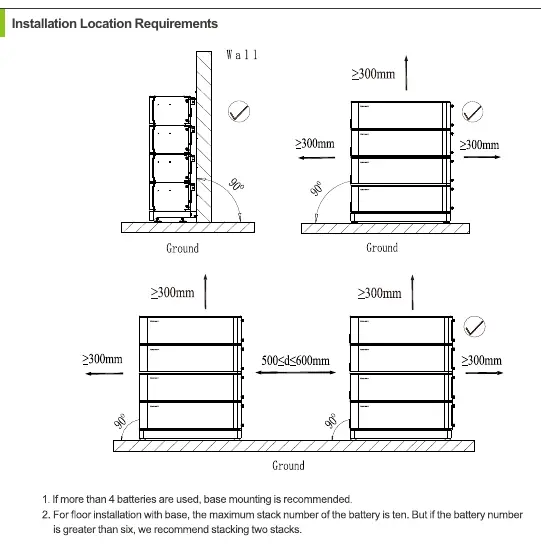
Floor installation
Use the ARK-2.5L-A1 Base for floor mounting. Ensure the location meets the required clearance distances (typically ≥300mm on sides and top). If the number of battery packs exceeds 7, install an additional safety part in the middle battery.
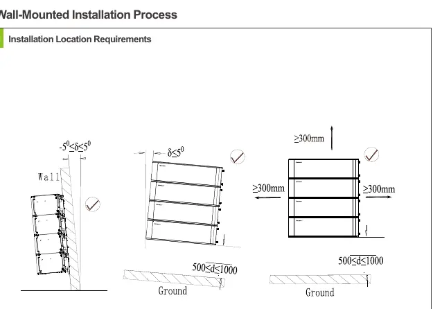
Wall-mounted installation
Ensure the wall weight capacity exceeds 150kg. The number of wall-mounted installations should not exceed four. Use the provided wall hangers and secure the battery modules horizontally.
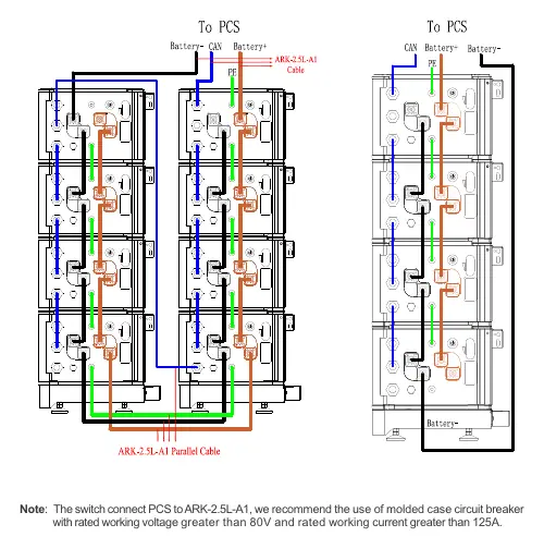
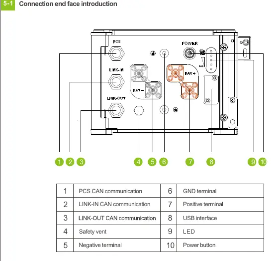
Wiring connection
The connection end face includes ports for PCS CAN communication, LINK-IN/OUT CAN communication, power terminals (positive/negative), and a USB interface. When connecting multiple battery modules in parallel, use the provided parallel cables. It is recommended to use a molded case circuit breaker with a rated working voltage greater than 80V and a rated working current greater than 125A between the PCS and the battery system.
Key operation
The power button controls the system state:
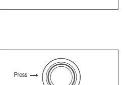
- Power on: Press and hold the button for ≥2 seconds.
- Shut down: Press the button once.
- Status check: Pressing for
The ALM/RUN light will turn green when the system is powered on.
Service and contact
For technical support, contact Shenzhen Growatt New Energy Co., Ltd. at 86 0755 2747 1942 or visit www.ginverter.com.
Official resources from the manual
Manufacturer information
Growatt New Energy
Practical help
Common problems
Wall mounting safety
Ensure the wall can support at least 150kg and do not exceed four stacked units.
Drilling hazards
Avoid drilling holes in areas where water pipes or electrical cables are buried.
System startup
When using multiple modules in parallel, you only need to press the power button on one module to start or shut down the entire system.
Before use
- Verify all items from the packing list are present.
- Ensure the installation environment temperature is between -10°C and +50°C.
- Check that the wall weight capacity exceeds 150kg for wall mounting.
- Ensure the circuit breaker between PCS and battery is rated >80V and >125A.
- Confirm the safety part is installed at the top battery (and middle if >7 batteries).
Specs in practice
- Circuit Breaker
- Recommended molded case circuit breaker with rated working voltage >80V and current >125A.
- Operating Temperature
- The system operates between -10°C and +50°C.
Images and diagrams
- The wiring diagram shows the connection between the PCS and the battery stack using parallel cables.
- The port layout identifies the PCS CAN, LINK-IN/OUT, power terminals, and USB interface.
- The installation procedure diagrams illustrate the stacking and securing of battery modules.
Model compatibility
- Maximum of 4 units for wall-mounted installation.
- If more than 7 battery packs are used, an additional safety part is required in the middle battery.

Manual page author
Emily Carter
User documentation editor
Prepares concise manual descriptions and highlights the most useful setup, operation, and maintenance information for readers.