Power / EV Chargers
Installation and User Guide for Growatt THOR 11/22AS-S-V1 EV Charger
Quick installation and user guide for the Growatt THOR 11/22AS-S-V1 three-phase AC EV charger. Includes wiring diagrams, app configuration, charging modes, and troubleshooting.
Table of contents
Manual images
Click an image to enlargeQuick guide from the manual
This document provides installation and operation instructions for the Growatt THOR 11/22AS-S-V1 three-phase AC EV charger. It covers physical installation, network configuration, charging modes, and troubleshooting. Installation should be performed by a qualified electrician in compliance with local regulations.
Product Description
The THOR series is an intelligent three-phase AC charger featuring a man-machine interface, control, billing, and communication functions. It supports connection to a back-office server for reservation and payment via the ShinePhone App. Communication options include Ethernet, WiFi, and 4G.
Installation and Wiring
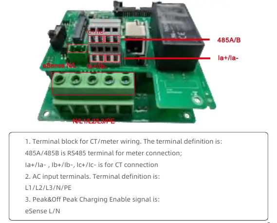
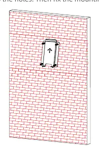
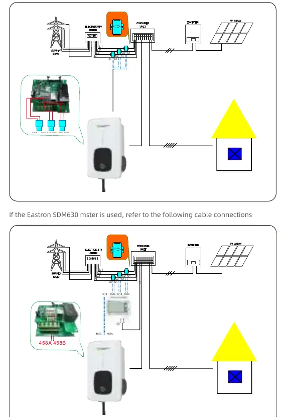
The charger can be mounted on a wall or a pole. Ensure the mounting surface is solid (concrete recommended for poles). Wiring involves connecting AC input cables (L1/L2/L3/N/PE) and communication wires (CT/meter/RS485) to the terminal block located in the side window. Always crimp insulated ferrule or ring terminals on the wire ends.
App Download and Configuration
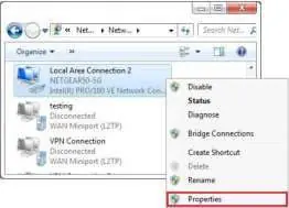
Download the ShinePhone App from the App Store or Google Play. Register an account and add the EV charger as a device. Internet configuration can be done via WiFi, network cable, or 4G. For WiFi setup, ensure the network is 2.4GHz and the signal strength is sufficient.
Charging Modes
The charger supports three main activation modes:
- APP mode: Initiate or cease charging via the ShinePhone App.
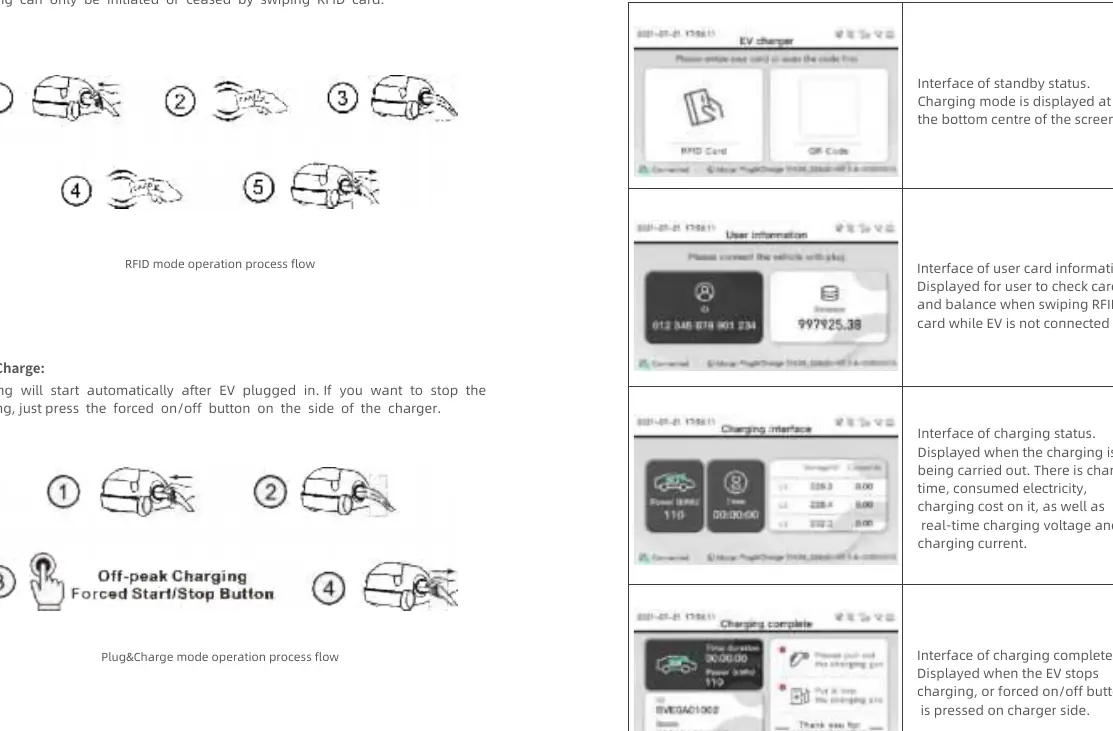
- RFID mode: Initiate or cease charging by swiping an RFID card.
- Plug&Charge: Charging starts automatically after the vehicle is plugged in.
Work Modes
- Fast Mode: Charges at maximum power from renewable energy or the grid.
- PV Linkage Mode: Charges dynamically using surplus solar power. Requires an external CT or meter to monitor power import/export.
- Off-peak Modes: Automatically charges during low-rate periods to reduce costs.
- Load Balancing: Adjusts charging power dynamically based on home power consumption to avoid tripping the main breaker.
Troubleshooting
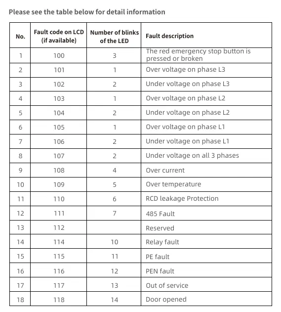
Faults are indicated by the LED indicator (number of blinks) or fault codes on the LCD. Common issues include emergency stop button activation, over/under voltage, over current, and communication failures. Refer to the troubleshooting table in the manual for specific fault descriptions and solutions.
Maintenance
Clean the surface with a soft, damp cloth. Do not use solvents or abrasives. Ensure the power is off before cleaning. Regularly check the cable and case for damage.
Manufacturer information
Growatt New Energy
Practical help
Common problems
Red emergency stop button pressed
Check if the button is pressed or broken.
Over/Under voltage on phases
Check the voltage levels on L1, L2, and L3.
WiFi connection failure
Ensure the router is 2.4GHz and signal strength is greater than -75dbm.
Charging not starting
Verify the charging mode (APP/RFID/Plug&Charge) and ensure the charger is authorized.
Before use
- Verify installation environment (hard surface/wall).
- Ensure a qualified electrician performed the wiring.
- Check the charger cable and case for physical damage.
- Download the ShinePhone App.
- Verify 2.4GHz WiFi availability for network configuration.
Specs in practice
- Rated voltage
- AC 400V (Three-phase).
- IP Protection
- IP65, suitable for outdoor and indoor use.
- Communication
- Ethernet, WiFi, and 4G connectivity options.
Images and diagrams
- Wiring definition: Shows terminal block for CT/meter, AC input, and eSense.
- Main circuit diagram: Illustrates connection of L1, L2, L3, N, PE and CT/meter.
Model compatibility
- Requires 2.4GHz WiFi for internet configuration.
- PV Linkage and Load Balancing require an external CT or meter (Acrel/Eastron).

Manual page author
David Miller
Documentation analyst
Organizes user manual content into clear summaries, with attention to model details, product context, and everyday usability.