Power / EV Chargers
User Manual for Growatt THOR 11AS-S-P EV Charger
Comprehensive user guide for the Growatt THOR 11AS-S-P and 22AS-S-P three-phase AC EV chargers. Includes installation, wiring, app configuration, charging modes, and troubleshooting.
Table of contents
Manual images
Click an image to enlargeQuick guide from the manual
The Growatt THOR series is an intelligent three-phase AC charger for electric vehicles. This manual provides instructions for installation, network configuration, and operation. Ensure the device is installed by a qualified professional and that the grid voltage matches the specifications (400V AC).
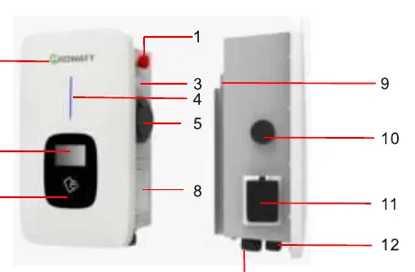
Product overview
The charger features an emergency stop button, status indicator, LCD screen, and RFID card reader. Connections include a side window for wiring, a mounting bracket, and cable glands for communication and AC input.
Installation and wiring
Wall mounting: Use the mounting bracket as a template to mark and drill holes. Fix the bracket to the wall, then secure the charger onto the bracket using the provided screws.
Pole mounting: The pole should be installed on a hard, concrete surface. Fix the pole with expansion bolts, then attach the mounting bracket and charger to the pole.
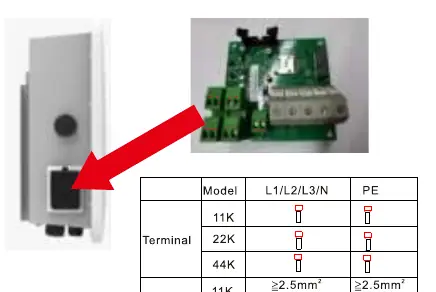
Wiring: Connect AC input wires to the terminal block inside the side window. Ensure correct crimping of insulated ferrules or ring terminals. Refer to the wiring diagram for specific terminal definitions (L1, L2, L3, N, PE).
App and network configuration
Download the ShinePhone app to manage the charger. Register an account and add the device by scanning the QR code or entering the serial number. Network configuration can be done via WiFi, network cable, or 4G. For WiFi, ensure a 2.4GHz network is available.
Charging modes and operation
The charger supports three main operation modes:
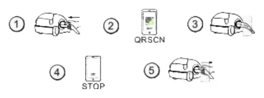
- APP/RFID mode: Initiate or stop charging via the ShinePhone app or by swiping an RFID card.
- Plug&Charge: Charging starts automatically when the EV is plugged in. Stop charging by pressing the forced on/off button.
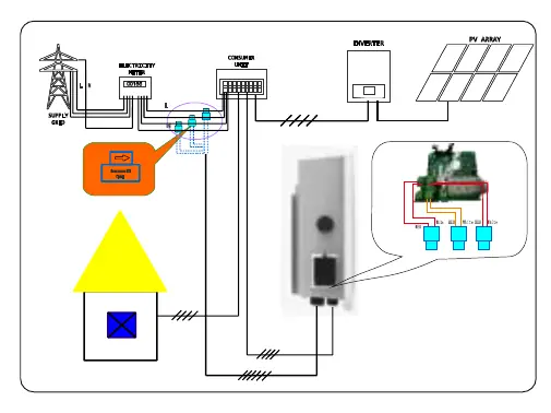
- PV Linkage mode: Uses surplus solar power to charge the vehicle. Requires an external CT or meter for power monitoring.
- Off-peak mode: Automatically charges during low-rate electricity periods to reduce costs.
Troubleshooting
If a fault occurs, check the LCD display or the number of blinks on the LED indicator. Common errors include:
- 100: Emergency stop button pressed or broken.
- 101-107: Over/Under voltage on phases L1, L2, or L3.
- 108: Over current.
- 109: Over temperature.
- 110: DC leakage current detected.
- 111: RS485 communication fault.
Specifications
The charger operates at 400V AC, 50Hz, with a maximum current of 16A or 32A. It is rated IP65 for protection and supports communication via Ethernet, WiFi, or 4G. Operating temperature range is -20°C to +50°C.

Manufacturer information
Growatt New Energy
Practical help
Common problems
Red emergency stop button pressed or broken
Check the status of the emergency stop button and reset if necessary.
Over/Under voltage errors
Verify the stability of the grid voltage supply.
RS485 communication fault
Check the wiring connections between the charger and the meter/CT.
DC leakage current detected
Inspect the charging cable and vehicle connection for faults.
Before use
- Ensure the mounting surface is solid (concrete recommended for pole mounting).
- Verify the grid voltage is 400V AC.
- Download the ShinePhone app.
- Ensure a 2.4GHz WiFi network is available for configuration.
- If using PV Linkage, ensure an external CT or meter is installed.
Images and diagrams
- The wiring definition diagram shows the terminal blocks for CT/meter and RS485 connections.
- The main circuit diagram illustrates the input, output, and internal protection components.
Model compatibility
- Requires 2.4GHz WiFi for network configuration.
- PV Linkage and Load Balancing functions require an external CT or meter.

Manual page author
David Miller
Documentation analyst
Organizes user manual content into clear summaries, with attention to model details, product context, and everyday usability.