Power / Solar Panels
User Manual for Growatt ARK High Voltage Battery System
Comprehensive user guide for the Growatt ARK High Voltage Battery System. Includes installation steps, wiring diagrams, safety instructions, operation, and troubleshooting for the HVC 60050-A1 and ARK 2.5H-A1 modules.
Table of contents
Manual images
Click an image to enlargeQuick guide from the manual
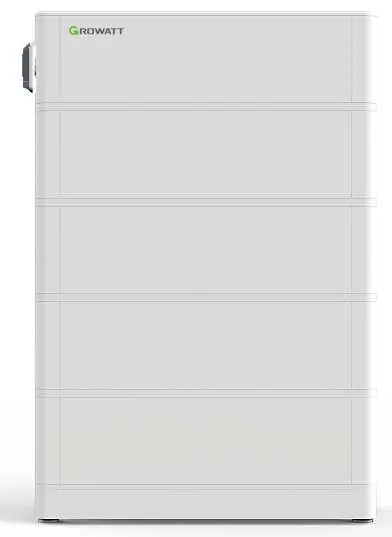
The Growatt ARK High Voltage Battery System consists of an HVC 60050-A1 controller module and multiple ARK 2.5H-A1 battery modules. This system is designed for energy storage and can be configured with 2 to 10 modules in series. Before installation, ensure you have the necessary protective equipment and that the wall or floor can support the weight of the system.
Product Overview
The system comprises two main components:
- HVC 60050-A1 (Controller Module): Manages the battery system, includes the DC breaker, and handles communication with the PCS (Power Conversion System).
- ARK 2.5H-A1 (Battery Module): Contains the battery cells, BMS, and connection ports.
Safety Instructions
Strict adherence to safety guidelines is required to prevent injury or damage:
- Do not disassemble or modify the battery system.
- Do not expose the battery to temperatures above 50°C or direct sunlight.
- Ensure the system is installed in a dry, well-ventilated area away from corrosive substances.
- Wear protective gear (insulating gloves, safety goggles, safety shoes) during installation.
- Ensure the DC breaker is in the OFF position before performing any maintenance or installation.
Installation
The system supports both wall-mounted and floor-standing installations.
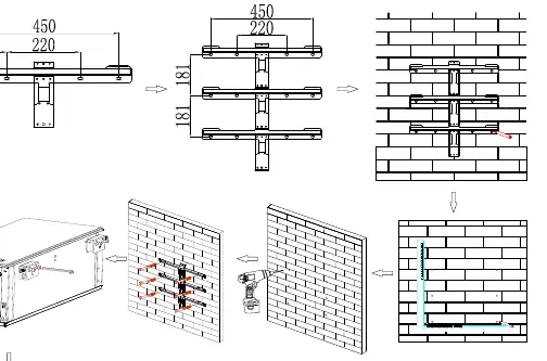
Wall Mounting
- Ensure the wall can support at least 150 kg.
- Maintain a minimum clearance of 300 mm from side walls and 500 mm from the floor.
- Use an 8 mm drill bit to create holes at least 60 mm deep.
- Secure the wall bracket and hang the battery, ensuring it does not swing.
Stand Mounting
- Place the battery base at the installation site.
- Secure the anti-tip plate to the wall.
- Stack the battery modules on the base and connect the fixing bars between modules.
- Ensure the stack is stable and tighten the safety screws.
Electrical Connection
Important: Always wear ESD-safe gear. Ensure the DC breaker is OFF.
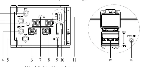
- Power Cables: Connect cables according to color coding. Ensure they click into place.
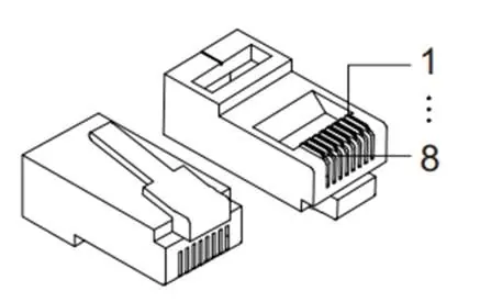
- Communication Cables: Connect the RJ45 cables between the HVC controller and the battery modules as specified in the wiring diagrams.
- Grounding: A 6 mm² grounding wire must be connected to the grounding port.
- Termination: Insert a dummy plug (blind plug) into the LINK 1 port of the last battery module.
Operation
To start the system, press and hold the POWER button for more than 5 seconds. The system is operational when the RUN/ALM and SOC lights are on. If the RUN/ALM light turns red, a fault has occurred.
Troubleshooting
The LED indicators provide status and error information:
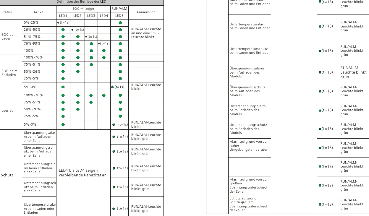
- RUN/ALM flashing green: Indicates a warning or specific protection state (e.g., over/under temperature, over/under voltage).
- RUN/ALM flashing red: Indicates a serious fault requiring professional intervention (e.g., short circuit, communication loss).
- RUN/ALM solid red: Indicates a critical system error (e.g., voltage sampling error, main circuit fault).
Maintenance
If the battery is not used for an extended period, charge it to 40% SOC every 6 months to maintain chemical properties. Before replacing any module, turn off the DC breaker and disconnect all cables.
Manufacturer information
Growatt New Energy
Practical help
Common problems
ALM light flashing green
Indicates a protection state like over/under temperature or voltage. Wait for the system to recover automatically or check environmental conditions.
ALM light flashing red
Indicates a serious fault such as a short circuit or communication loss. Stop operation and contact a technician.
System does not start
Check that the DC breaker is in the ON position and that all power and communication cables are securely connected.
Before use
- Verify the wall/floor can support the system weight (min 150kg for wall).
- Ensure all battery modules are the same model and batch.
- Check that the voltage difference between modules is <= 0.5V.
- Wear protective gear (gloves, goggles, safety shoes).
- Ensure the DC breaker is OFF before starting installation.
Specs in practice
- Nominal Voltage
- 51.2V per ARK 2.5H-A1 module.
- Communication
- Uses CAN protocol for communication with the PCS.
Images and diagrams
- Wiring Diagram: Shows the connection sequence between the HVC controller and battery modules.
- LED Indicators: Explains the status of SOC and RUN/ALM lights for different operating modes.
Model compatibility
- Requires HVC 60050-A1 controller module.
- Supports 2 to 10 ARK 2.5H-A1 modules in series.

Manual page author
Michael Turner
Technical manual editor
Reviews PDF manuals for structure, safety notes, and practical product details so readers can find the right information quickly.