Tools / Generators
Growatt MOD 10KTL3-X Inverter Quick Guide
Comprehensive installation and operation guide for the Growatt MOD 10KTL3-X series three-phase on-grid inverter, covering electrical connections, safety, and system monitoring.
Table of contents
Manual images
Jump to the sectionProduct Overview
The Growatt MOD 10KTL3-X is a high-efficiency three-phase on-grid inverter designed for residential and commercial solar power systems. The unit features a compact design with a front panel, touch button interface, and an integrated LCD screen for real-time monitoring. It is equipped with a DC switch for safety, multiple PV terminals for string connections, and various communication ports including RS485 and USB for system integration and data management.
Installation Requirements
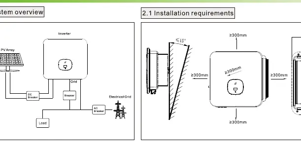
Proper installation is critical for the performance and longevity of the inverter. Ensure there is at least 300mm of clearance around the unit to allow for adequate heat dissipation. The mounting surface must be stable and capable of supporting the weight of the inverter. When drilling holes for wall mounting, always verify the location of hidden electrical wires and water pipes to prevent damage. The inverter should be installed in a location that avoids direct sunlight and extreme weather conditions.
Electrical Connection
Before beginning any electrical work, ensure all switches are in the OFF position. The system requires a protective grounding wire, AC output cables, and PV input cables. Use the recommended cable sizes to ensure safety and efficiency. The PV input terminals must be connected with correct polarity, and the voltage must not exceed 1100V. The AC output connection involves a multi-core cable connected to the grid. Always verify that the PV input voltage and current are within the specified MPPT limits before turning on the inverter.
Operation and Monitoring
The inverter is operated via a touch button on the front panel. A single touch cycles through the display screens, while a double touch allows you to enter settings. The LED indicator provides immediate status feedback: a steady green light indicates normal operation, a red light signals a fault, and a flashing red light serves as a warning. Users can monitor key data such as PV voltage, power output, and total energy generation directly on the LCD screen.
Post-Installation and Maintenance
After installation, perform a thorough check to ensure all connections are secure and the inverter is properly grounded. Verify that all switches are functional and that there are no loose wires or exposed terminals. Regular maintenance involves checking the ventilation areas for dust or debris and ensuring the communication cables are intact. If a fault occurs, refer to the LED status indicators and the troubleshooting guidelines to identify and resolve the issue. Always follow local grid regulations when configuring export limits or other advanced settings.
Manufacturer information
Growatt New Energy
Practical help
Common problems
Inverter shows a red LED status
Check for system faults and refer to the LCD screen for specific error codes or messages.
PV voltage too high
Ensure the input voltage is below 1100V and within the MPPT limits specified in the manual.
Loose cable connection
Ensure all terminals are clicked into place and cables are securely fastened during installation.
Before use
- Ensure all switches are in the OFF position before wiring.
- Verify that the mounting surface can support the inverter weight.
- Check that there is at least 300mm clearance around the unit.
- Confirm PV input voltage is less than 1100V.
- Ensure correct polarity for all DC connections.
- Verify that the grounding wire is properly connected.
- Perform a final check of all cable connections for tightness.
Specs in practice
- PV Input Voltage
- The DC voltage supplied by solar panels; must be under 1100V.
- Export Limit
- A setting to restrict the amount of power fed back into the grid.
Images and diagrams
- System overview showing the connection between PV array, inverter, grid, and load.
- Wall mounting template showing required spacing and dimensions.
- AC output connection steps for secure wiring.
- PV input terminal installation showing positive and negative polarity.
- Communication module installation and removal process.
Model compatibility
- Compatible with standard RS485 communication protocols.
- Designed for use with three-phase grid systems.
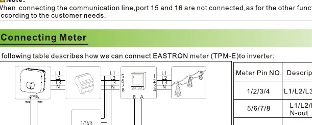
- Supports connection to external meters like the EASTRON TPM-E.

Manual page author
Michael Turner
Technical manual editor
Reviews PDF manuals for structure, safety notes, and practical product details so readers can find the right information quickly.