Smart Home / Smart Relays
User Manual for Heatit ZM Single Relay 16A
Quick guide for the Heatit ZM Single Relay 16A. Includes installation instructions, wiring diagrams, Z-Wave inclusion/exclusion steps, and technical specifications.
Quick answers from the manual
Quick answer
- The Heatit ZM Single Relay 16A is a Z-Wave Plus relay for in-wall installation, supporting loads up to 16A/3600W. It allows control via Z-Wave or a wired switch and includes power metering. p. 1
Key actions
- Add/Remove device from Z-Wave network p. 1
Problems and fixes
LED shows red light for 3 seconds
The adding process was unsuccessful. Perform a 'remove device' process and try again.
p. 1Maintenance and reset
- Resetting parameters p. 1
Technical specifications
| Parameter | Value | Meaning | Pages |
|---|---|---|---|
| Max load | 3600W | Resistive load limit | p. 1 |
| Max current | 16A | Maximum electrical current | p. 1 |
Where to find it in the PDF
- Quick Guide p. 1
Table of contents
Manual images
Click an image to enlargeQuick guide from the manual
The Heatit ZM Single Relay 16A is a high-power relay designed for in-wall installations. It allows you to control connected devices via a Z-Wave network or a wired switch. The module features a 16A relay and scene controller functionality, supporting a maximum load of 16A/3600W at 230VAC.
Installation and Wiring
Warning: Installation must be performed by a qualified electrician in accordance with national building codes. Always disconnect power to the device from the mains before installation.
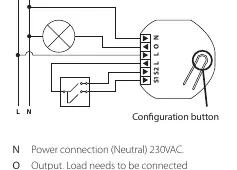
Use 1.5mm² to 2.5mm² cables for the mains power connection. The wiring terminals are as follows:
- N: Neutral connection (230VAC).
- O: Output. Connect the load between O and Neutral.
- L: Power connection (Live) 230VAC.
- S1: Switch 1, used to control the internal relay.
- S2: Switch 2, used as a scene controller. Note: In toggle mode, S2 must not be connected.
Inclusion and Exclusion
To add or remove the device from your Z-Wave network:
- Set your primary controller to add/remove mode (secure or non-secure).
- Press the configuration button or the switch connected to S1 three times in rapid succession.
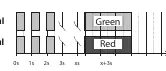
- The device LED will blink green when the procedure is initiated.
- If successful, the LED will stay green for 3 seconds.
- If unsuccessful, the LED will show a red light for 3 seconds. Perform the remove process and try again.
Adding/removing mode is indicated by a flashing green light, which lasts for 90 seconds or until the device is added/removed.
Technical Specifications
- Protocol: Z-Wave Plus, 868.4MHz
- Chip: Z-Wave 700 chip
- Rated Voltage: 230VAC 50Hz
- Max Load: 3600W (resistive load), 750W (self-limiting heating cable)
- Max Current: 16A
- Ambient Temperature: 5°C to 40°C
- IP Code: IP20
- Dimensions: 46 x 45 x 25mm
Practical help
Common problems
Device not adding to network
Ensure the controller is in add mode, then press the S1 switch or configuration button 3 times rapidly. If the LED turns red, perform a 'remove device' process first.
S2 switch not working
Ensure you are not using toggle mode, as S2 cannot be connected in this mode.
Before use
- Disconnect mains power before starting installation.
- Ensure the load does not exceed 16A/3600W.
- Use 1.5mm² to 2.5mm² cables for mains power.
- Verify the primary controller supports Z-Wave Plus.
Images and diagrams
- N: Neutral terminal.
- O: Output terminal for the load.
- L: Live terminal (two provided for looping).
- S1/S2: Inputs for external switches.
Model compatibility
- Compatible with all Z-Wave Plus certified devices.
- Functionality depends on the primary controller's implementation.

Manual page author
Michael Turner
Technical manual editor
Reviews PDF manuals for structure, safety notes, and practical product details so readers can find the right information quickly.