Smart Home / Smart Relays
Heatit ZM Single Relay 16A Installer's Manual
Comprehensive installer's manual for the Heatit ZM Single Relay 16A. Includes wiring diagrams, Z-Wave network inclusion steps, configuration parameters, and safety features.
Quick answers from the manual
Quick answer
- The Heatit ZM Single Relay 16A is a high-power relay for in-wall installations, allowing control of connected devices via Z-Wave or a wired switch. It supports a maximum load of 16A/3600W. p. 1, 6
Key actions
- Add/Remove device p. 1, 2
- Factory Reset p. 2, 3
First start
- Power on the device and set the primary controller to add mode. Press the configuration button or S1 switch 3 times. p. 1, 2
Problems and fixes
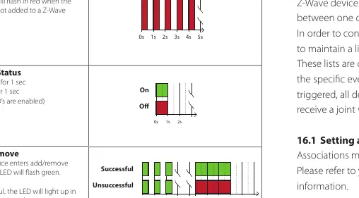
LED blinks red for 3 seconds
Inclusion or removal failed. Perform a 'remove device' process and try again.
p. 2Maintenance and reset
- The device is maintenance-free. Factory reset is performed by holding the configuration button for 20 seconds. p. 2, 3, 6
Technical specifications
| Parameter | Value | Meaning | Pages |
|---|---|---|---|
| Rated voltage | 230VAC 50Hz | Operating voltage | p. 6 |
| Max Load | 16A / 3600W | Maximum power capacity | p. 1, 6 |
| Dimensions | 45 x 45 x 25mm | Physical size | p. 6 |
Where to find it in the PDF
- Installation and Wiring p. 2
- Configuration Parameters p. 4
Table of contents
Manual images
Click an image to enlargeQuick guide from the manual
The Heatit ZM Single Relay 16A is a high-power relay designed for in-wall installations. It allows control of connected devices via a Z-Wave network or a wired switch. The device supports a maximum load of 16A/3600W at 230VAC.
Installation
Warning: Installation must be performed by a qualified electrician in accordance with national building codes. Always disconnect power to the device mains before installation.
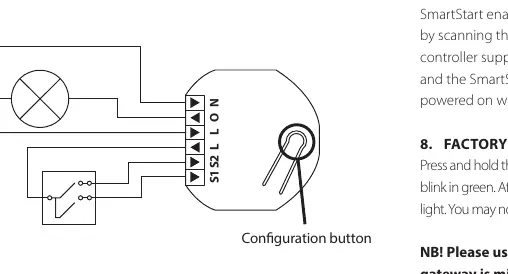
The device supports wiring with a cross-section of 1x2.5mm². It can be wired to either a Single Wall Switch or a Double Wall Switch.
- N: Power connection (Neutral) 230VAC.
- O: Output. Load must be connected between O and Neutral.
- L: Power connection (Live) 230VAC.
- S1: Switch 1, used to control the internal relay.
- S2: Switch 2, used as a scene controller. Note: In toggle mode, S2 must not be connected.
Z-Wave Network Inclusion
The device can be added to a Z-Wave network using two methods:
- Standard (Manual): Set the primary controller to add mode. Press the configuration button or the switch connected to S1 three times in rapid succession. The LED will blink green when the procedure is initiated.
- SmartStart (Automatic): Scan the Z-Wave QR-Code on the product if your primary controller supports SmartStart. The device will be added automatically after being powered on.
Switch Modes
The device supports two types of switches:
- Momentary Switch (NO) - Default: Recommended mode allowing full feature usage, including HOLD and RELEASE functions for central scenes.
- Toggle Switch (ON/OFF): In this mode, the relay and switch state may not always be equal. Note that using toggle mode disables S1 inclusion, scene controller commands, and association groups 3 and 5.
Configuration Parameters
The device behavior can be customized using configuration parameters:
- Parameter 1 (Load limit): Sets the maximum current (1-16A).
- Parameter 2 (Power shutdown actions): Defines behavior after overload/overheating.
- Parameter 3 (Switch Type): Selects between Momentary (0) or Toggle (1) switch.
- Parameter 6 (Restore Power Level): Sets relay state after power restoration (Always OFF, Always ON, or Restore last state).
- Parameter 7 & 8: Automatic turn OFF/ON timers.
- Parameter 9: Inverted Output.
Safety Features
The device includes built-in protection:
- Overload Protection: Triggers if power draw exceeds 16A for >2 seconds or >20A for 0.2 seconds. The relay cuts power to prevent failure.
- Overheating Protection: Internal temperature sensor prevents overheating from external high loads.
If a safety feature is triggered, the relay cuts power. To clear the state, the relay must be switched back on manually via Z-Wave or the connected switch.
Factory Reset
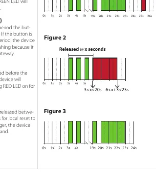
Press and hold the configuration button. After 3 seconds, the LED will blink green. After 20 seconds, the LED will stop blinking and emit a constant light. Release the button. Use this procedure only when the primary controller is missing or inoperable.
Practical help
Common problems
Device not added to network
Ensure the primary controller is in add mode. Press the configuration button or S1 switch 3 times. If the LED lights up red for 3 seconds, inclusion failed; perform a 'remove device' process and try again.
Overload/Overheating protection triggered
The relay cuts power. Check the connected load. Manually switch the relay back on via Z-Wave or the connected switch once the condition is resolved.
Factory reset not working
Ensure the button is held for exactly 20 seconds until the LED emits a constant light. If held longer, the command is ignored.
Before use
- Disconnect mains power before starting installation.
- Ensure installation is performed by a qualified electrician.
- Verify the Z-Wave controller is in add/remove mode before attempting inclusion.
- Check that the switch type (Momentary vs Toggle) matches your physical setup.
- If using Toggle mode, ensure S2 is not connected.
Specs in practice
- Z-Wave 700 chip
- The wireless communication protocol used by the device.
Images and diagrams
- The wiring diagram shows the connection points for L (Live), N (Neutral), O (Output), S1 (Switch 1), and S2 (Switch 2).
- The configuration button is located on the device housing.
Model compatibility
- Compatible with all Z-Wave Plus certified devices.
- Requires a security-enabled Z-Wave Controller to fully utilize S2 security features.

Manual page author
David Miller
Documentation analyst
Organizes user manual content into clear summaries, with attention to model details, product context, and everyday usability.