Smart Home / Smart Relays
Installation Guide for Schneider Electric Wiser 16A Relay
Installation guide for the Schneider Electric Wiser 16A Relay for temperature control. Includes wiring diagrams, installation steps, and technical specifications.
Quick answers from the manual
Quick answer
- The Wiser 16A Relay is a device used to control electric heaters or electric underfloor heating systems within the Wiser smart home ecosystem. p. 1
Key actions
- Install the relay in a wall-mounted box and connect the wiring according to the diagram. p. 1
- Configure the device using the Wiser app after installation. p. 1
Problems and fixes
Risk of electric shock
Disconnect power supply before installation and ensure qualified personnel perform the work.
p. 1Technical specifications
| Parameter | Value | Meaning | Pages |
|---|---|---|---|
| Rated voltage | 230 V, 50 Hz | Operating voltage | p. 1 |
| Load | 16A resistive / 3A inductive | Maximum switching capacity | p. 1 |
Where to find it in the PDF
- Installation and Technical Data p. 1
Table of contents
Manual images
Click an image to enlargeQuick guide from the manual
The Wiser 16A Relay is designed to control electric heaters or electric underfloor heating systems. It is a component of the Wiser system and requires proper installation by a qualified professional due to the risk of electric shock and arc flash. Always disconnect the power supply before performing any installation work.
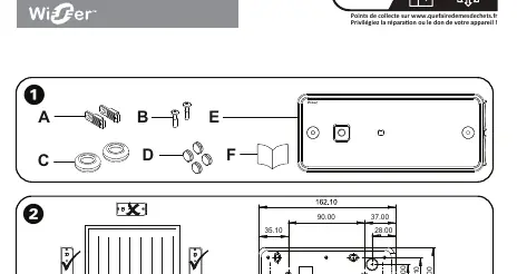
Package contents
- Wiser 16A Relay
- 2x cable clamps
- 2x cable clamp screws
- 2x cable plugs
- 4x blanking plugs
- Instruction leaflet
Installation
Device positioning: The relay should be installed in a suitable location, typically in a wall-mounted box. Ensure the floor sensor is positioned correctly if used for underfloor heating.
Preparation of the mounting surface: Use the provided breakout tabs for mounting holes and cable entry. Ensure the floor sensor is placed at least 1m from the edge of the room and halfway between heating pipes.
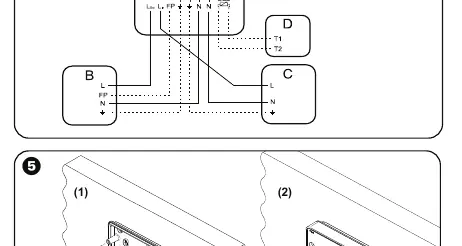
Wiring connection
DANGER: Risk of electric shock, explosion, or arc flash. Installation must be performed by skilled professionals. Ensure the power is disconnected before starting.
Steps:
- Pierce the rubber grommets with a small screwdriver and thread the cable through. The cable sheath length should be approximately 6.5 mm.
- Connect the wires to the connector blocks and ensure the screws are tightened.
- Secure the cable with the cable clamps and screws provided in the package.
- Ensure the cable clamps are positioned correctly to provide strain relief.
Final installation

- Secure the relay to the wall-mounted box using the provided screws.
- Ensure the rubber grommets are seated properly in the mounting plate.
- Place the two blanking plugs on the front surface.
Technical data
- Rated voltage: 230 V, 50 Hz (AC only)
- Load: 16A resistive or 3A inductive
- Protection: IP44
- Communication: Zigbee 3.0
- Operating temperature: 0°C to 60°C
- Class: Class II
Manufacturer information
Schneider Electric
Practical help
Common problems
Electric shock or arc flash during installation
Ensure power is disconnected from the supply before starting any work. Installation must be performed by a qualified professional.
Conductor damage
Ensure the cable sheath length is approximately 6.5 mm and that cable clamps are used to secure the cable properly.
Sensor not working correctly
Ensure the floor sensor is not placed on top of heating pipes and is positioned at least 1m from the room edge.
Before use
- Verify the power supply is disconnected.
- Ensure the installation location is suitable and not behind a wall-mounted heater.
- Check that the cable sheath is stripped to 6.5 mm.
- Confirm the load does not exceed 16A resistive or 3A inductive.
- Ensure all rubber grommets are properly seated.
Images and diagrams
- The wiring diagram shows the connection points for L (Live), N (Neutral), Load, and Sensor.
- The diagram illustrates the use of cable clamps to secure the wiring.
Model compatibility
- Compatible with Wiser system.
- Requires specific floor sensors for underfloor heating applications.

Manual page author
Michael Turner
Technical manual editor
Reviews PDF manuals for structure, safety notes, and practical product details so readers can find the right information quickly.