Smart Home / Smart Plugs & Strips
SwitchBot Relay Switch User Manual
Comprehensive user manual for the SwitchBot Relay Switch. Includes detailed wiring diagrams for 100-240V AC and 12-48V DC power supplies, installation safety guidelines, technical specifications, and factory reset procedures.
Quick answers from the manual
Quick answer
- The SwitchBot Relay Switch is a smart relay for controlling electrical loads. It supports 100-240V AC and 12-48V DC power supplies and requires professional installation. p. 1, 3, 4, 5
Key actions
- Reset to factory settings p. 6
- Install the device p. 4, 5
First start
- Download the SwitchBot app, register an account, and follow in-app instructions. p. 2
Maintenance and reset
- Press and hold the device button for 15 seconds to restore factory settings. p. 6
Technical specifications
| Parameter | Value | Meaning | Pages |
|---|---|---|---|
| Max AC Output Current | 16 A | Maximum load for AC circuits | p. 6 |
| Max DC Output Current | 10 A | Maximum load for DC circuits | p. 6 |
Where to find it in the PDF
- Installation Guide p. 4, 5
- Specifications p. 6
Table of contents
Manual images
Click an image to enlargeQuick guide from the manual
The SwitchBot Relay Switch is a smart device designed to control electrical loads. It supports both AC (100-240V) and DC (12-48V) power supplies. Installation must be performed by a professional in accordance with local electrical regulations. The device requires the SwitchBot app for setup and operation.
Safety Information
- Professional Installation: This product involves high-voltage electricity and must be installed by a professional.
- Environment: Do not use in humid environments, outdoors, or in hot/overheating places. Protect from moisture.
- Installation Location: Install inside appliances or concealed boxes; do not install in areas easily accessible by hand.
- Load Limits: Maximum AC load current is 16 A. Ensure connected appliances do not exceed rated power.
- Safety Precautions: Do not disassemble or modify. If abnormal conditions (smoke, heat, strange odors) occur, switch off the main power supply immediately.
Installation
The device features terminals for O (Load output), I (Load input), SW (Switch input), 12V, L (Live), N (Neutral), and +/GND for DC.
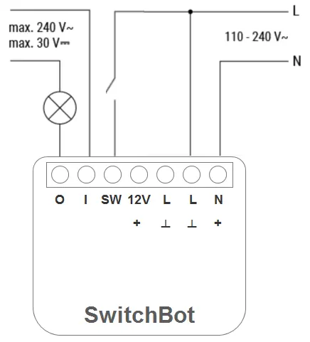
100-240 V AC Power Supply
- Connect the Live wire to the L terminal and the Neutral wire to the N terminal.
- Connect the switch to the SW terminal and the Live wire.
- Connect the load circuit to the I and O terminals.
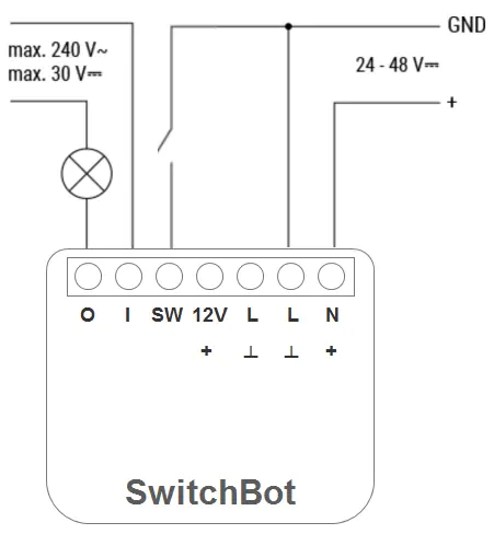
24-48 V DC Power Supply
- Connect the + wire to the + terminal and the GND wire to the I terminal.
- Connect the switch to the SW terminal and the GND wire.
- Connect the load circuit to the I and O terminals.
12 V DC Power Supply
Follow the 24-48V DC steps, but connect the 12V+ wire to the 12V terminal instead of the + terminal.
Reset to Factory Setting
To restore factory settings, press and hold the device button for 15 seconds. Note that this operation will clear all historical data and settings.
Specifications
- AC Input: 100 to 240 V, 50/60 Hz
- DC Input: 12 V, 24 to 48 V
- Max AC Output Current: 16 A
- Max DC Output Current: 10 A
- Connectivity: IEEE 802.11 b/g/n (2.4 GHz Wi-Fi), Bluetooth Low Energy
- Operating Temperature: -20 °C to 40 °C
Practical help
Common problems
Device not responding or malfunctioning
Check all wiring connections against the diagrams and ensure the power supply is within the rated limits.
Electromagnetic interference
Do not use the device near electronic equipment that handles high-precision controls or weak signals.
Overheating or abnormal conditions
Switch off the main power supply immediately and remove the product.
Before use
- Ensure the main power supply is turned off before starting installation.
- Verify that your power supply (AC or DC) matches the supported voltage ranges.
- Download the SwitchBot app from the App Store or Google Play Store.
- Register for a SwitchBot account.
- Ensure the installation location is not easily accessible by hand.
Specs in practice
- Max AC Output Current
- 16 A - The maximum electrical current the device can handle for AC loads.
- Max DC Output Current
- 10 A - The maximum electrical current the device can handle for DC loads.
- Connectivity
- Supports 2.4 GHz Wi-Fi and Bluetooth Low Energy for remote control.
Images and diagrams
- Wiring diagrams are provided for 100-240V AC, 24-48V DC, and 12V DC configurations.
- Terminals O and I are for the load circuit.
- Terminal SW is for the switch input.
Model compatibility
- Requires 2.4 GHz Wi-Fi network.
- Not suitable for outdoor use.
- Designed for use at altitudes below 2000 meters.

Manual page author
Emily Carter
User documentation editor
Prepares concise manual descriptions and highlights the most useful setup, operation, and maintenance information for readers.