Tools / Power Tools
HiKOKI G 12SA3 / G 13SB3 Disc Grinder User Manual
Quick guide for the HiKOKI G 12SA3 and G 13SB3 disc grinders. Includes safety instructions, assembly, operation techniques, maintenance, and parts diagrams.
Table of contents
Manual images
Jump to the sectionQuick Guide
This manual provides essential instructions for the safe and efficient operation of the HiKOKI G 12SA3 and G 13SB3 disc grinders. Before using the tool, ensure the power source matches the nameplate specifications, the switch is in the OFF position, and the wheel guard is securely attached. Always wear appropriate personal protective equipment, including eye and ear protection.
Safety Warnings
General Safety: Keep the work area clean and well-lit. Do not operate in explosive atmospheres. Keep children and bystanders away. Use personal protective equipment such as dust masks, non-skid safety shoes, and hard hats.
Grinding and Cutting Safety: Use only recommended wheel types. The guard must be securely attached. Do not use damaged accessories. Hold the tool by insulated gripping surfaces when performing operations where the cutting accessory may contact hidden wiring. Never lay the tool down until the accessory has come to a complete stop.
Kickback Prevention: Maintain a firm grip and position your body to resist kickback forces. Use the auxiliary handle. Avoid bouncing or snagging the accessory, especially when working on corners or sharp edges.
Specifications
- Power Input: 1300 W
- No-load Speed: 11000 /min
- Wheel Diameter: 115 mm (G 12SA3) / 125 mm (G 13SB3)
- Weight: 1.9 kg
Operation
Pressure: Do not overload the machine by applying excessive pressure. The weight of the machine alone is usually sufficient for effective grinding.
Grinding Angle: Hold the machine at an angle of 15°–30° so that the external edge of the wheel contacts the material at an optimum angle.
Technique: For new wheels, perform initial grinding by drawing the grinder across the workpiece toward the operator. Once the edge is abraded, grinding can be conducted in either direction.
Assembly
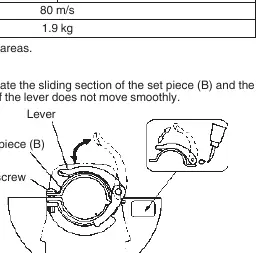
Wheel Guard: Ensure the guard is properly fitted and fastened. For tool-less guards, tighten the M5 screw to secure the guard while the lever is in the closed position.
Depressed Center Wheel: Turn the grinder upside down. Align the wheel washer with the spindle. Fit the wheel onto the washer, screw on the wheel nut, and tighten it using the supplied wrench while holding the push button to lock the spindle.
Maintenance
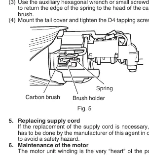
Carbon Brushes: These are consumable parts. Replace them when they are worn to or near the "wear limit." Keep them clean and ensure they slide freely in the brush holders.
General Maintenance: Regularly inspect all mounting screws and retighten if loose. Ensure ventilation openings are kept clear. If the supply cord needs replacement, it must be done by an authorized agent to avoid safety hazards.
Manufacturer information
HiKOKI
Practical help
Common problems
Tool does not start
Check if the plug is connected, the switch is in the ON position, or if the carbon brushes are worn out.
Excessive vibration
Check if the grinding wheel is mounted correctly, damaged, or if the mounting screws are loose.
Wheel binds or kicks back
Reduce pressure, ensure the workpiece is properly supported, and maintain the correct grinding angle (15-30 degrees).
Before use
- Verify the power source matches the tool's nameplate voltage.
- Ensure the power switch is in the OFF position before plugging in.
- Inspect the grinding wheel for cracks or surface defects.
- Ensure the wheel guard is securely attached and adjusted.
- Confirm the push button is disengaged before switching the tool on.
- Wear eye and ear protection, and other necessary PPE.
Specs in practice
- No-load speed
- 11000 rotations per minute.
- Wheel diameter
- 115 mm for G 12SA3, 125 mm for G 13SB3.
Images and diagrams
- Fig 1: Wheel guard adjustment using the lever and M5 screw.
- Fig 2: Correct grinding angle (15-30 degrees) and direction of movement.
- Fig 3: Assembly sequence for the depressed center wheel, washer, and nut.
- Fig 5: Carbon brush replacement procedure, including spring and holder details.
Model compatibility
- Do not use accessories not specifically designed and recommended by the manufacturer.
- Do not use separate reducing bushings or adapters for large hole abrasive wheels.
- Ensure the thread in the wheel is long enough to accept the spindle length for threaded hole wheels.

Manual page author
Michael Turner
Technical manual editor
Reviews PDF manuals for structure, safety notes, and practical product details so readers can find the right information quickly.