Tools / Power Tools
Operating Instructions for Hilti AG 125-15DB Angle Grinder
Quick guide for the Hilti AG 125-15DB angle grinder. Includes safety instructions, assembly, operation, maintenance, and troubleshooting.
Table of contents
Manual images
Click an image to enlargeQuick guide from the manual
This guide provides essential information for the safe and efficient use of the Hilti AG 125-15DB angle grinder. Always read the full documentation before initial operation. Key safety requirements include wearing eye protection, using the auxiliary handle, and ensuring the guard is correctly positioned. Always disconnect the power plug before making adjustments or changing accessories.
Product Overview
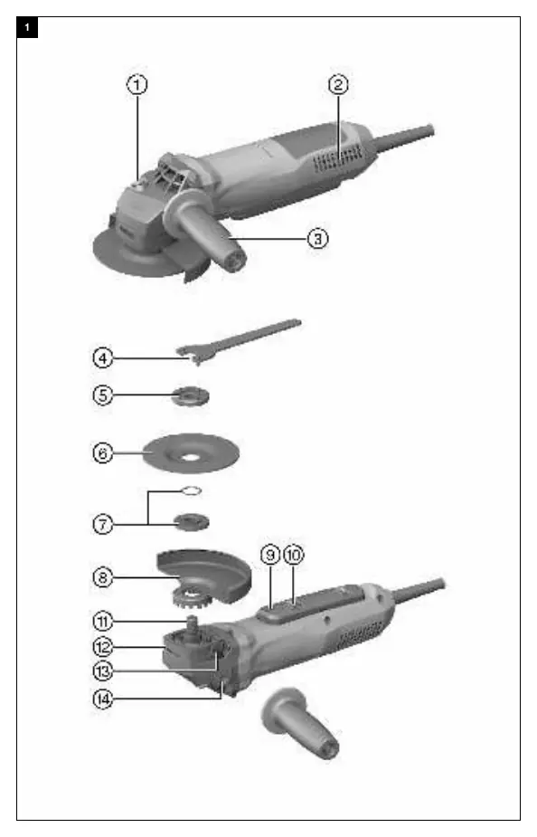
The Hilti AG 125-15DB is a hand-held electric angle grinder designed for cutting, grinding, and sanding metal and mineral materials without the use of water. Key features include an integrated brake, starting current limiter, constant-speed electronics, Active Torque Control (ATC), and restart interlock.
Safety
General Power Tool Safety: Keep the work area clean and well-lit. Do not operate in explosive atmospheres. Ensure the power plug matches the outlet.
Kickback and Related Warnings: Kickback is a sudden reaction to a pinched or snagged rotating wheel. Maintain a firm grip and position your body to resist kickback forces. Never place your hand near the rotating accessory.
Grinding and Cutting Safety: Use only recommended wheel types and the specific guard designed for the selected wheel. Do not grind with the side of a cut-off wheel.
Assembly

- Side Handle: Screw the side handle into one of the threaded bushings provided.
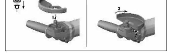
- Guard: Fit the guard onto the arbor collar, aligning the triangular marks. Press the guard release button and rotate until it engages.
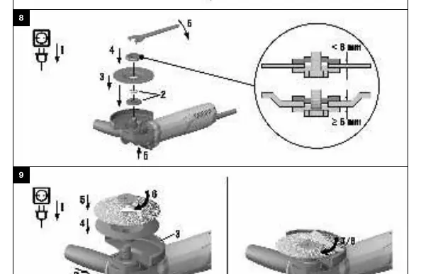
- Discs: Ensure the O-ring is in place in the clamping flange. Fit the flange, the disc, and the clamping nut. Use the pin wrench to tighten the nut while holding the spindle lockbutton.
Operation
Switching On: Plug the supply cord into the outlet. Slide the safety lock forward to unlock the on/off switch, then fully depress the switch.

Cutting: Apply moderate feed pressure and do not tilt the product or the cutting disc (hold at approx. 90° to the cutting plane).
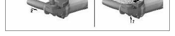
Rough Grinding: Move the product to and fro while maintaining a 5° to 30° angle of attack and applying moderate pressure.
Care and Maintenance
Always unplug the supply cord before carrying out maintenance. Clean air vents with a dry brush. Use a slightly damp cloth to clean the casing; do not use silicone-based cleaning agents. Repairs to electrical components must be carried out by trained electrical specialists.
Troubleshooting
If the product does not start, check the power supply, the supply cord/plug, and the carbon brushes. If the product is overloaded, release the switch and press it again, then allow it to run under no load for 30 seconds.
Manufacturer information
Hilti Corporation
Practical help
Common problems
Product does not start
Check power supply, inspect supply cord/plug for defects, or have carbon brushes checked by a specialist.
Product does not work
Product is overloaded. Release the on/off switch, press it again, and allow the product to run under no load for approx. 30 seconds.
Product does not develop full power
The extension cord conductor cross-section is inadequate. Use an extension cord with an adequate cross-section.
Elevated temperatures at the gear housing
Short braking interval. Allow the device to run under no load until it has cooled down.
Before use
- Wear eye protection
- Ensure the side handle is fitted
- Check that the guard is securely attached
- Verify the disc is undamaged and appropriate for the application
- Check that the O-ring is present and undamaged in the clamping flange
Specs in practice
- Maximum disc diameter
- 125 mm
- Thread diameter
- M14x1.5
Images and diagrams
- 1: Spindle lockbutton
- 9: On/off switch
Model compatibility
- Use only synthetic-resin-bonded, fiber-reinforced discs
- Max grinding disc thickness: 6.4 mm
- Max cutting disc thickness: 3 mm

Manual page author
Michael Turner
Technical manual editor
Reviews PDF manuals for structure, safety notes, and practical product details so readers can find the right information quickly.