Computers / Laptops
Maintenance and Service Guide for HP OmniBook 5 14-inch Laptop
Comprehensive maintenance and service guide for the HP OmniBook 5 14-inch Laptop. Includes component identification, removal and replacement procedures, BIOS setup, diagnostics, and technical specifications.
Table of contents
Manual images
Click an image to enlargeQuick guide from the manual
This guide provides essential maintenance and service information for the HP OmniBook 5 14-inch Laptop. It covers component identification, disassembly procedures, and system recovery. Always follow electrostatic discharge (ESD) precautions before opening the device.
Product description
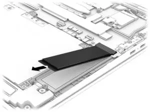
The HP OmniBook 5 14-inch Laptop features various configurations with Intel or AMD processors. Memory is onboard and not upgradeable. Storage is provided via M.2 2280 NVMe SSDs.
Removal and replacement procedures
Before servicing, ensure the computer is shut down and disconnected from power. Use a magnetic Phillips P1 screwdriver, tweezers, and a nonconductive pry tool.
Customer Self-Repair parts
Users can replace the AC adapter, bottom cover, and battery. Follow the specific steps for each component to avoid damage.
Authorized service provider parts
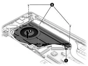
Components such as the system board, heat sink, display assembly, and WLAN module should only be accessed by authorized service providers.
BIOS and Diagnostics
Access the Setup Utility (BIOS) by pressing F10 during startup. Use HP PC Hardware Diagnostics (Windows or UEFI) to troubleshoot hardware failures.
Battery care
If a battery becomes swollen, discontinue use. Swelling is a result of gas generation and is not a safety issue, but the battery should be replaced.
Manufacturer information
HP Inc.
Practical help
Common problems
Battery swelling
Discontinue use and contact HP for a replacement.
System not booting
Use HP Recovery USB flash drive to restore the system.
BIOS access
Restart the computer and press F10.
Before use
- Shut down the computer completely.
- Disconnect the power cord and all external devices.
- Use a static-free work surface.
- Wear a wrist strap to prevent ESD.
- Have a magnetic Phillips P1 screwdriver ready.
Images and diagrams
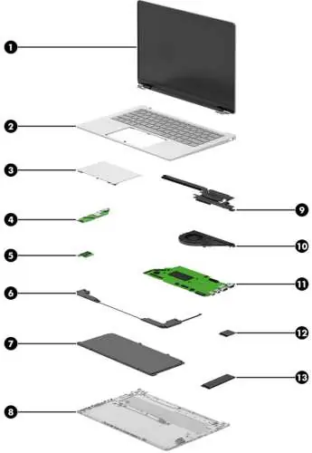
- Major components diagram for identifying internal parts.
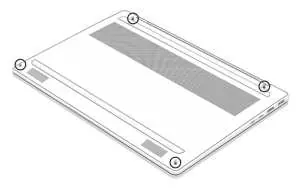
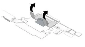
- Bottom cover removal steps.
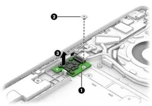
- SSD and WLAN module removal procedures.
- System board and display assembly disassembly steps.
Model compatibility
- Intel and AMD models use different system boards and WLAN modules.
- Memory is onboard and not upgradeable.

Manual page author
David Miller
Documentation analyst
Organizes user manual content into clear summaries, with attention to model details, product context, and everyday usability.