Computers / Laptops
Maintenance and Service Guide for HP OmniBook 7 14-inch Laptop
Comprehensive maintenance and service guide for the HP OmniBook 7 14-inch Laptop. Includes detailed instructions for component removal, replacement, system diagnostics, BIOS settings, and technical specifications.
Table of contents
Manual images
Click an image to enlargeImportant information from the manual
This guide provides essential maintenance and service information for the HP OmniBook 7 14-inch Laptop (models 14-kk0xxx and 14-kh0xxx). It covers component identification, removal and replacement procedures, system diagnostics, and technical specifications. Always follow electrostatic discharge (ESD) precautions when handling internal components.
Product description
The HP OmniBook 7 14-inch Laptop features various configurations including AMD Ryzen processors, integrated Radeon graphics, and multiple display options (2.2K, 2.8K, or WUXGA). Memory is onboard and not upgradeable. Storage is provided via M.2 2280 PCIe NVMe SSDs.
Getting to know your computer
The laptop includes various ports and indicators:
- Right side: USB Type-C power/Thunderbolt/10 Gbps ports, HDMI port, and AC adapter/battery light.
- Left side: USB 5 Gbps port and audio combo jack.
- Display: Includes integrated cameras, microphones, and WLAN antennas.
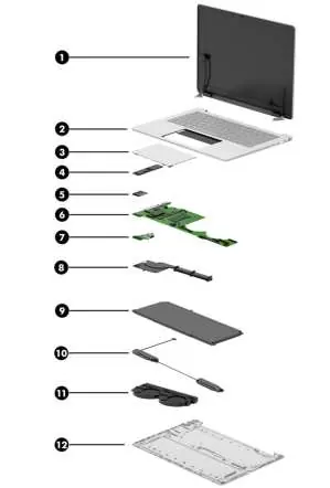
Illustrated parts catalog
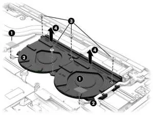
This section lists major components available for service, including the display assembly, top cover with keyboard, touchpad, SSD, WLAN module, system board, I/O board, heat sink, battery, and fans. Spare part numbers are provided for each component.
Removal and replacement procedures
Procedures are divided into Customer Self-Repair (CSR) and Authorized Service Provider parts. Always prepare the computer for disassembly by shutting it down, disconnecting power, and removing external devices. Key procedures include:
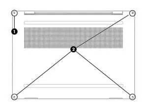
- Bottom cover: Loosen the captive screw and remove non-captive screws to release the cover.
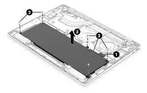
- Battery: Disconnect the battery cable from the system board before removal. Use a revive kit when installing a new battery.
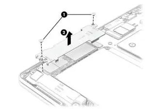
- SSD: Remove the cover and pull the drive out of the socket.
- WLAN module: Disconnect antenna cables and remove the securing screw.
- System board: Requires removal of the SSD, WLAN module, and various internal cables.
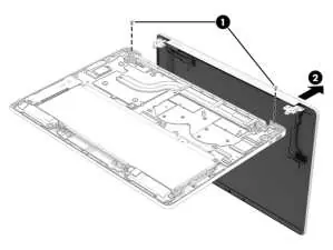
- Display assembly: Involves removing hinges and separating the display from the chassis.
Backing up, restoring, and recovering
Use Windows tools or the HP Cloud Recovery Download Tool to create recovery media. If the system fails to boot, you can use the HP Recovery USB flash drive or HP Sure Recover to restore the OS image.
Using HP PC Hardware Diagnostics
The computer includes diagnostic tools to identify hardware failures. These can be accessed via Windows (HP Support Assistant) or UEFI (BIOS). If a failure is detected, a 24-digit failure ID code is generated for support assistance.
Specifications
Key specifications include:
- Dimensions: 314.0 mm x 226.5 mm x 18.9 mm (max height).
- Weight: 1413 g.
- Operating temperature: 5°C to 35°C (41°F to 95°F).
- Storage: PCIe NVMe M.2 2280 SSDs.
Battery care and recycling
If you notice battery swelling, stop using the notebook and contact HP for replacement options. Swollen batteries are not a safety issue but result from normal degradation. Recycle used electronic hardware and batteries according to local laws.
Manufacturer information
HP Inc.
Practical help
Common problems
Computer not starting
Check BIOS Event Log or use HP PC Hardware Diagnostics to identify hardware failures.
Battery swelling
Stop using the notebook immediately and contact HP for replacement options.
System not responding
Press and hold the power button for at least 10 seconds to force a shutdown.
Before use
- Ensure the computer is turned off and disconnected from power.
- Use a magnetic Phillips P1 screwdriver.
- Use a nonconductive, nonmarking pry tool.
- Discharge static electricity before handling internal components.
- Place the computer on a hard, flat surface.
Specs in practice
- Operating voltage
- 5V to 20V DC depending on the port and device.
- Operating temperature
- 5°C to 35°C (41°F to 95°F).
Images and diagrams
- Exploded view of major components on page 22.
- Bottom cover removal steps on page 36.
- Battery removal and replacement steps on pages 39-44.
Model compatibility
- Customer Self-Repair parts are specific to the model.
- Display assemblies are only available as subcomponents.

Manual page author
Michael Turner
Technical manual editor
Reviews PDF manuals for structure, safety notes, and practical product details so readers can find the right information quickly.