Tools / Air Compressors & Pneumatics
Husky 230VAC Air Compressor Wiring Instructions
A comprehensive wiring and installation guide for Husky 230VAC air compressors. This manual covers electrical connection requirements, wire sizing charts, grounding procedures, and step-by-step instructions for wiring the pressure switch.
Quick answers from the manual
Quick answer
- This document provides wiring instructions for Husky 230VAC air compressors, including wire sizing, grounding requirements, and step-by-step pressure switch installation. p. 1, 2
Key actions
- Wiring the pressure switch p. 2
- Grounding the compressor p. 1
First start
- Rotate the switch knob on and off several times to ensure proper rotation before providing electrical power. p. 2
Show 3 more answers Show less
Problems and fixes
Switch cover does not fit
Verify wire lengths inside the switch are as short as possible.
p. 2Technical specifications
| Parameter | Value | Meaning | Pages |
|---|---|---|---|
| Ground screw torque | 25-30 in/lbs | Required torque for ground wire connection | p. 2 |
| Terminal screw torque | 22-26 in/lbs | Required torque for terminal screws | p. 2 |
| Cord clamp torque | 15-25 in/lbs | Required torque for cord clamp screw | p. 2 |
| Wire size (C602H) | 10-Gauge | Recommended wire size for 3.7HP model | p. 1 |
| Wire size (C801H/C803H) | 8-Gauge | Recommended wire size for 5HP model | p. 1 |
Where to find it in the PDF
- Wiring Instructions and Wire Size Chart p. 1
- Pressure Switch Wiring Steps p. 2
Table of contents
Manual images
Click an image to enlargeImportant Safety Information
Electrical installation and service must be performed by a qualified electrician who is familiar with all applicable electrical codes. Improper grounding can result in electrical shock, severe injury, or death. Always ensure the power is shut off and confirmed with a voltage meter before performing any work.
Electrical Requirements
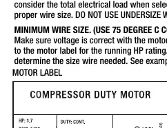
The motor rating and power supply must have compatible voltage, phase, and hertz characteristics. Use 75 degree C copper wire. Do not use undersized wire, as this can cause excessive voltage drop during start-up and damage the motor. If the lead wire is longer than 6 ft, consult a local electrician for alternative wiring options.
Wire Size Chart
- Model C602H: 10-Gauge wire (3.7HP)
- Model C801H/C803H: 8-Gauge wire (5HP)
Time delay or "slow-blow" fuses are recommended to handle the momentary starting current of the electric motor.
Pressure Switch Wiring Instructions
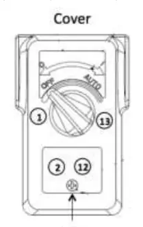
- Turn the switch to the "off" position.
- Loosen the Phillips head screw and remove the cover.
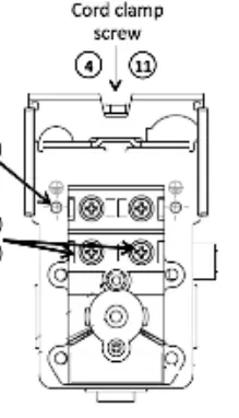
- Loosen the cord clamp on the rear of the switch and route the correct gauge wire through the clamp opening. Keep the wire length as short as possible.
- Install the ground wire to the pressure switch metal body using the supplied ground screw. Torque to 25-30 in/lbs.
- Loosen both screws marked as "line" on the pressure switch.
- Install/crimp insulated fork terminals to the black and white wires.
- Slide the fork terminals into the proper location in the pressure switch and tighten screws to 22-26 in/lbs.
- Pull on wires to confirm connections are tight and terminals are crimped properly.
- Verify wire lengths inside the switch are as short as possible to allow the cover to be re-installed.
- Tighten the cord clamp screw to 15-25 in/lbs.
- Install the pressure switch cover and tighten the screw.
- Rotate the switch knob on and off several times to ensure proper rotation before providing power.
Grounding
Grounding reduces the risk of electric shock by providing an escape wire for the electric current. Ground terminals are identified with a ground symbol and/or the letters G, GR, or PE. Ensure good bare metal contact at all grounding connection points.
Manufacturer information
Husky
Practical help
Common problems
Motor is electrically 'starved'
Ensure the supply wires are not too small. Using undersized wires causes excessive voltage drop.
Switch cover will not fit
Verify that wire lengths inside the switch are as short as possible. If they are too long, the cover cannot be installed.
Switch knob does not rotate freely
Verify the wire lengths again inside the switch; they may be obstructing the mechanism.
Before use
- Confirm electrical power is shut off using a voltage meter.
- Verify the motor nameplate is rated for the voltage being used (e.g., 208V vs 230V).
- Ensure a qualified electrician is performing the installation.
- Select the correct wire gauge based on the model (10-gauge or 8-gauge).
- Ensure all grounding connections have good bare metal contact.
Show more Show less
Specs in practice
- Ground screw torque
- 25-30 in/lbs
- Terminal screw torque
- 22-26 in/lbs
- Cord clamp screw torque
- 15-25 in/lbs
Images and diagrams
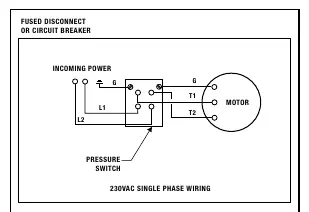
- The wiring diagram shows the connection from the incoming power through the fused disconnect/circuit breaker to the pressure switch and motor.
- Grounding is indicated with the 'G' symbol, connecting the incoming ground to the motor and pressure switch.
Model compatibility
- 230 volt single phase motors do not work on 208 volts unless they have a specific 208 volt rating on the nameplate.

Manual page author
Emily Carter
User documentation editor