General / Service Manuals
Illustrated Parts List for Husqvarna ST 121E Snow Thrower
Comprehensive illustrated parts list for the Husqvarna ST 121E snow thrower, including detailed assembly diagrams and component identification for the auger, chute, handle, drive, and engine systems.
Table of contents
Quick guide from the manual
This document is an illustrated parts list for the Husqvarna ST 121E snow thrower (Product Number 961 83 00-01). It provides exploded view diagrams and corresponding part numbers for all major assemblies. Use this guide to identify specific components for maintenance or repair. Always use Original Equipment Manufacturer (O.E.M.) replacement parts to ensure safety, maintain performance, and protect your warranty.
Important safety and usage notes
- All component dimensions are provided in U.S. inches (1 inch = 25.4 mm).
- Failure to use O.E.M. parts can be hazardous, cause damage to the equipment, and void the warranty.
Assembly diagrams
The manual contains detailed exploded views for the following systems:
- Auger Assembly: Includes blade, bearing support, ball bearing, and auger weldment.
- Chute Assembly: Includes chute, deflector, wing knob, and cap plunger.
- Handle Assembly: Includes LED subassemblies, wiring harness, control shroud, and cable components.
- Drive Assembly: Includes idler arm, pulleys, belt, and clutch cable.
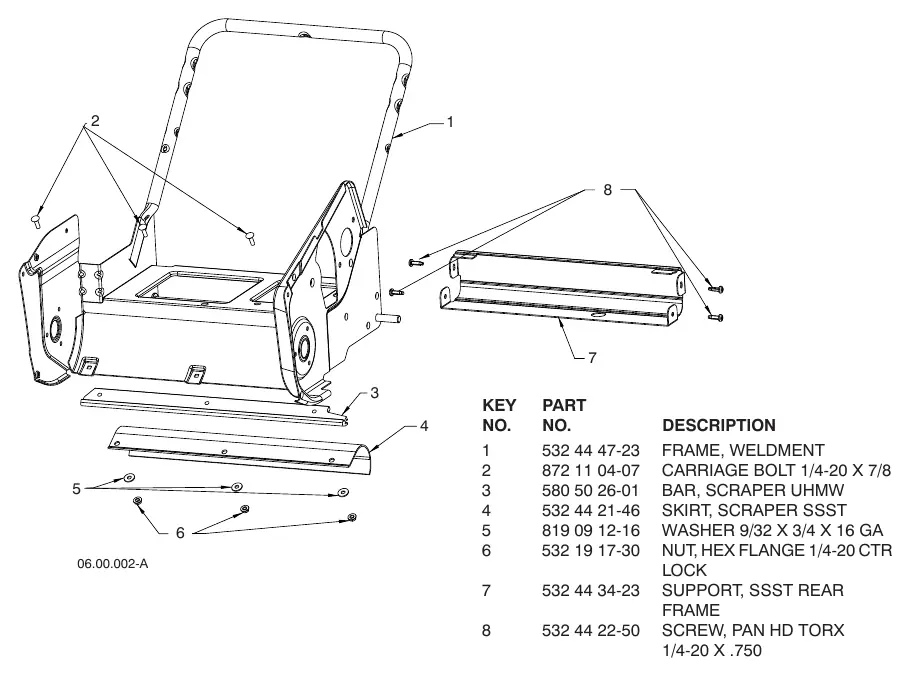
- Frame Assembly: Includes scraper bar, skirt, and wheels.
- Shroud Assembly: Includes plenum, covers, and exhaust plate.
- Engine Assembly (LCT 208CC): Detailed breakdown of the engine components, including carburetor, starter, ignition coil, and cylinder assembly.
Manufacturer information
Husqvarna
Practical help
Common problems
Damage or wear to auger components
Refer to the Auger Assembly diagram to identify and replace specific parts like the blade, bearing support, or roll pin.
Drive system failure
Check the Drive Assembly diagram to inspect the belt, idler pulley, and clutch cable for wear or misalignment.
Engine starting or performance issues
Consult the Engine Assembly section to identify parts such as the primer bulb, spark plug, or fuel tank assembly.
Before use
- Verify the model number (ST 121E) and product number (961 83 00-01) match your machine.
- Ensure all fasteners are tightened according to specified torque values (e.g., drive assembly screws).
- Check that all safety guards and shrouds are properly installed.
- Inspect the scraper bar and chute for any obstructions or damage.
Specs in practice
- 1 inch = 25.4 mm
- Conversion factor for all component dimensions listed in the manual.
- Torque 13-18 FT-LBS
- Required tightening torque for specific drive assembly screws.
Images and diagrams
- Each assembly page features an exploded view diagram with numbered keys.
- The corresponding table lists the Key No., Part No., and Description for every component shown in the diagram.
Model compatibility
- Parts are specific to Husqvarna ST 121E (961 83 00-01).
- Engine parts are specific to the LCT 208CC engine model 442159.
- Some parts, such as the electric starter, have specific versions (e.g., European 230V).

Manual page author
Michael Turner
Technical manual editor
Reviews PDF manuals for structure, safety notes, and practical product details so readers can find the right information quickly.