Industrial / Air Purifiers
User Manual for IGM Magnetic Base for M3 Feeder 141-QH03
Quick guide and user manual for the IGM Magnetic Base for M3 Feeder (141-QH03). Includes assembly instructions, operation steps, safety guidelines, and maintenance tips.
Table of contents
Manual images
Click an image to enlargeQuick Guide from the Manual
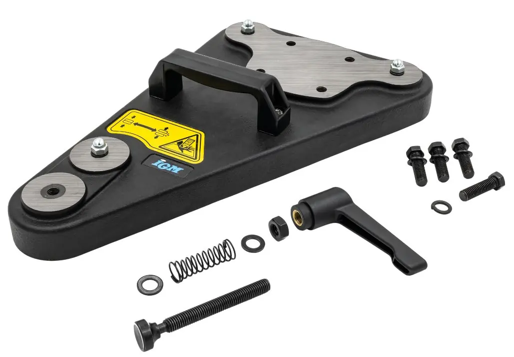
This manual provides instructions for the IGM Magnetic Base for M3 Feeder (141-QH03). This accessory is designed exclusively for mounting an M3 feeder to a cast iron or steel table. Ensure you read all safety guidelines before operation to prevent injury or damage to the equipment.
Safety Information
- Warning: Do not use this accessory if you have a pacemaker.
- Keep hands and fingers away from under the base to avoid pinching.
- The base contains strong magnets; keep away from magnetized objects like credit cards, computers, and televisions.
- Maximum temperature resistance is 80°C; recommended operating conditions are below 70°C.
- Do not operate near flammable liquids or gases.
- Always ensure the base is firmly attached before use.
Technical Specifications
- Dimensions: 367 x 231 x 136 mm
- Weight: 5.4 kg
- Maximum Magnet Force (3pcs): 450 kg
- Maximum Material Thickness: 40 mm
- Minimum Material Width after Cutting: 45 mm
Assembly
Tools required: 17 mm wrench.

- Remove the base from the box and place it on a non-magnetic or insulating surface.
- Secure the locking handle (A) onto the locking screw (B) using the 17mm wrench to tighten the hex nut (C).
- Rotate the locking handle to extend the locking screw. Keep the screw extended when the base is not attached to prevent accidental magnetic connection.
- Mount the feeder base (A) to the magnetic base using the four provided M10 screws and spring washers (B).
- Move the base with the mounted feeder by grabbing the feeder arm and the handle on the base.
Operation
- Disconnect the machine from the power supply before starting.
- Remove the blade guard and lower the saw blade into the table.
- Adjust the rip fence according to the material size.
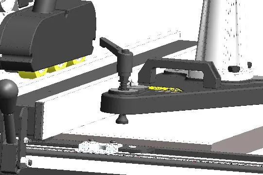
- Place the magnetic base to the right of the feed direction. Ensure the locking screw is extended before placement.
- Once positioned, rotate the locking handle until the locking screw is completely retracted. Verify the base is securely attached by hand.
- Connect the feeder to the power supply and confirm correct feeding.
- Adjust the saw blade height; it must not exceed material thickness by more than 3 mm.
Recommendations and Limits
- Material width after cutting should not exceed 230 mm if the base is attached at the edge of the table.
- Minimum material width after cutting is 45 mm to prevent roller damage.
- Use material up to 40 mm wide to avoid excessive resistance. If resistance is too high, reduce saw blade speed or feed rate.
Maintenance and Cleaning
- Disconnect the machine from the power supply before maintenance.
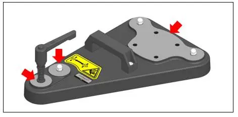
- Before each use, check for loose screws or damage.
- After each use, vacuum dust and scraps from the accessory and surrounding area.
- Wipe with a dry cloth; use resin remover if resin has built up.
- Regularly apply a layer of anti-corrosion oil to the mounting plate, locking screw, and magnets.
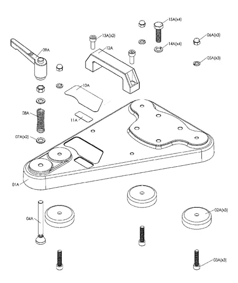
Parts List
Refer to the exploded view diagram for part identification, including the baseplate, magnets, handles, and various screws/washers.
Manufacturer information
IGM Tools & Machinery
Practical help
Common problems
Base is shifting or unstable
Reduce saw blade speed or feed rate to lower resistance. Ensure the base is securely attached.
Roller damage
Ensure material width after cutting is at least 45 mm.
Accidental magnetic connection
Keep the locking screw extended when the base is not attached to the table.
Before use
- Check the technical condition of the accessory for any damage.
- Ensure all safety covers are mounted.
- Verify the machine is disconnected from the power supply during setup.
- Ensure the surface is stable and well-lit.
- Check that the locking screw is extended before placing the base.
Specs in practice
- Maximum Magnet Force
- 450 kg total force provided by the 3 magnets.
- Maximum Material Thickness
- 40 mm is the maximum thickness allowed for the workpiece.
- Minimum Material Width
- 45 mm after cutting to prevent damage to the rollers.
Images and diagrams
- Exploded view shows the assembly of the baseplate, magnets, and handle components.
- Procedural diagrams illustrate the correct positioning of the base relative to the saw blade and rip fence.
- Maintenance diagrams highlight parts requiring anti-corrosion oil.
Model compatibility
- Designed only for mounting M3 feeder.
- Compatible only with cast iron or steel tables.
- Do not use with other types of feeders.

Manual page author
David Miller
Documentation analyst
Organizes user manual content into clear summaries, with attention to model details, product context, and everyday usability.