Tools / Woodworking Tools
User Manual for IGM 151-DX3 DriftMaster Fence System
Quick guide for the IGM 151-DX3 DriftMaster Fence System. Includes assembly, mounting options, drift adjustment, scale calibration, and maintenance procedures.
Table of contents
Manual images
Click an image to enlargeQuick guide from the manual
The IGM 151-DX3 DriftMaster Fence System is a precision accessory for bandsaws. This manual provides instructions for assembly, mounting, and calibration. Key operations include adjusting the fence for parallelism, perpendicularity, and blade drift. Always disconnect the machine from the power supply before performing any assembly, repairs, or maintenance.
Product description and parts
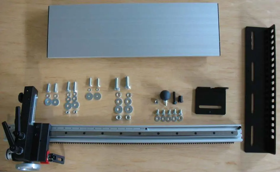
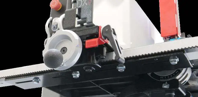
The system consists of the main fence, a rack and pinion rail with a scale, an adjustment assembly, and various mounting brackets. Familiarize yourself with the components before assembly. The fence features a drift lock, fence lock knobs, a fence travel lock, and a drift knob for precise control.
Setup and assembly
Approximate assembly and setup time is 30 minutes. Follow these steps:
- Insert the scale into the front channel of the rail with the desired measuring system (inches or mm) facing up.
- Screw the black stop stud into the hole on the right side and tighten with a hex key.
- Install the black knob into the handwheel and tighten the nut.
- Loosen the two black fence lock knobs, slide the fence onto the rail, and tighten the knobs.
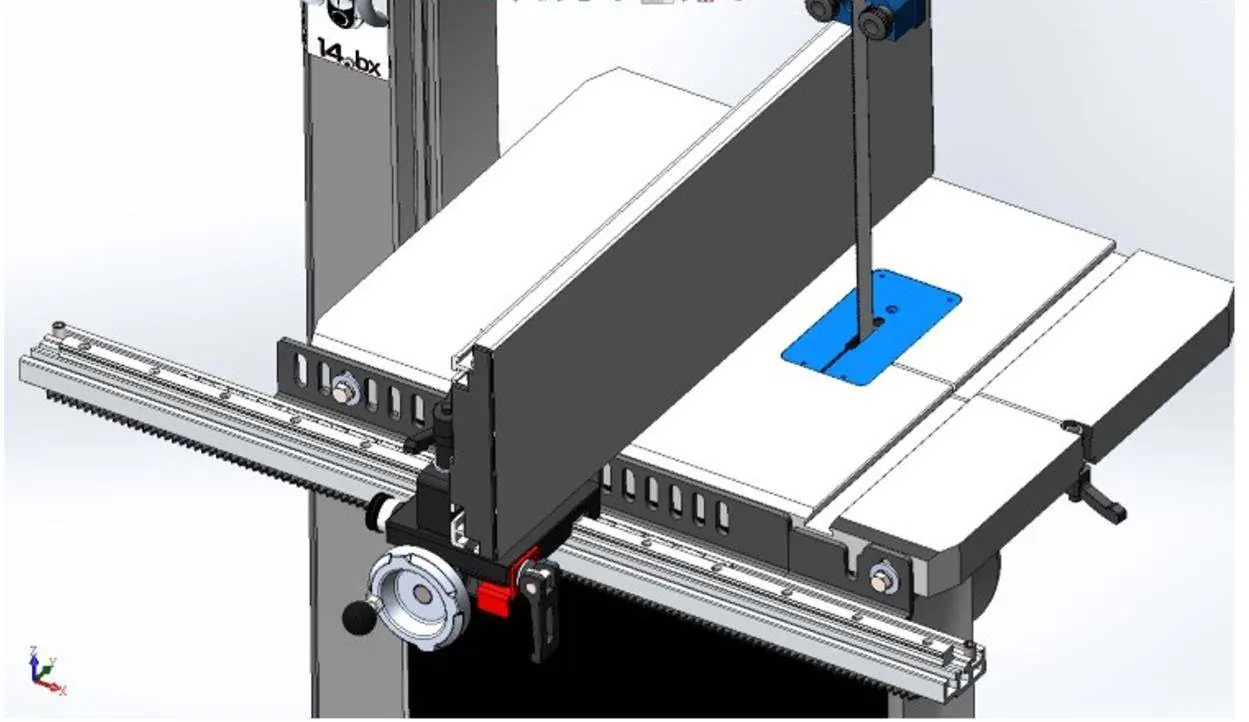
Fence mounting
There are multiple mounting options depending on your bandsaw model. Ensure the mounting bracket is not placed over the blade changing slot in the table. If the large bracket extends over the table, it may be attached without the small bracket. If your saw lacks pre-drilled holes, you may need to drill them to align with the mounting brackets. Ensure the rail is parallel to the edge of the tabletop.
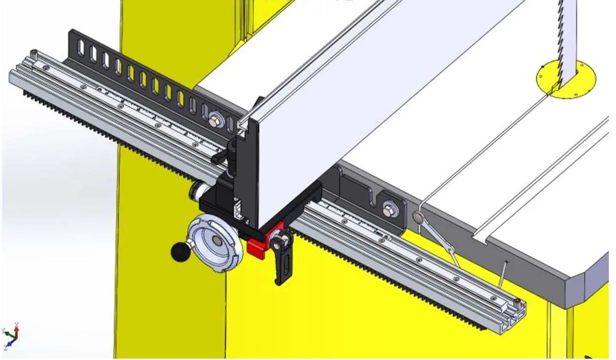
Fence operation
The fence can be moved forward and backward by loosening the two fence lock knobs. It can be repositioned to a horizontal position by loosening these same knobs. To move the fence left or right, loosen the fence travel lock and rotate the handwheel. One full rotation moves the fence approximately 7 mm. For quick movement, lift the lock lever for micro-adjustment and extend the red slider.
Adjustments
Parallelism and perpendicularity
If the fence is not parallel to the table, loosen the mounting bolts and use the set screws on the right side to raise the rail. If the fence is not perpendicular (90°) to the table, use the two set screws located between the fence lock knobs to adjust the tilt.
Drift adjustment
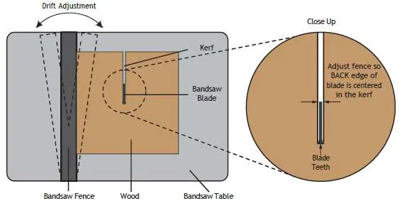
To adjust for blade drift: loosen the drift locks, rotate the drift knob to set the fence parallel to the blade, and re-lock. Perform a test cut on a piece of wood at least 250 mm long and 12 mm thick. Inspect the back edge of the blade in the kerf; it should be centered. Adjust the drift knob and repeat until the blade is centered.
Scale adjustment
After tensioning the blade and adjusting for drift, move the fence close to the blade. Measure the distance with a ruler and slide the scale to match this measurement. Tighten the screws on both sides of the scale, being careful not to overtighten.
Maintenance
Regular maintenance is required to keep the system in good working order:
- Keep the fence clean.
- Apply light grease to the adjusting screw for drift and fence tilt once per month.
- Apply light grease to the worm gear once per month.
- Periodically check that all nuts and bolts are tight.
Manufacturer information
IGM Tools & Machinery
Practical help
Common problems
Fence is not parallel to the bandsaw table
Loosen the mounting bolts and use the set screws on the right side to raise the rail until parallel.
Fence is not perpendicular (90°) to the table
Slightly loosen the two fence lock knobs and use the set screws between them to tip the fence left or right.
Blade drift during cutting
Adjust the fence parallel to the blade drift using the drift knob and verify with a test cut.
Before use
- Check all parts for damage upon unpacking.
- Ensure the machine is disconnected from the power supply.
- Verify that the mounting bracket is not positioned over the blade changing slot.
- Ensure the rail is parallel to the edge of the tabletop.
- Confirm the blade is sharp, properly tensioned, and tracked.
Specs in practice
- Fence Length
- 578 mm
- Maximum Fence Travel
- 660 mm for LAGUNA bandsaws (rail travel max 740 mm)
- Travel per One Rotation
- Approximately 7 mm
Images and diagrams
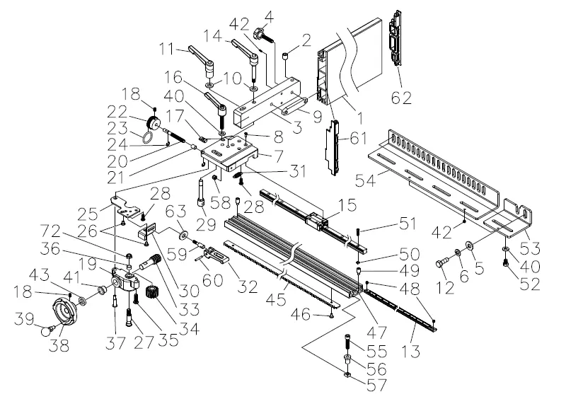
- The parts list diagram identifies all components by index number for assembly reference.
- The drift adjustment diagram illustrates how to center the back edge of the blade in the kerf.
Model compatibility
- Mounting hardware is included for various bandsaws (Laguna, Jet, Powermatic, Rikon).
- If included hardware does not fit your specific saw configuration, additional material may need to be purchased separately.

Manual page author
Emily Carter
User documentation editor
Prepares concise manual descriptions and highlights the most useful setup, operation, and maintenance information for readers.