HVAC / Ventilation Systems
User Manual for Innova 100H Heat Recovery Unit
Comprehensive installation, operation, and maintenance guide for the Innova 100H high-efficiency heat recovery unit. Includes wiring diagrams, mounting instructions, and troubleshooting.
Table of contents
Manual images
Click an image to enlargeQuick guide from the manual
This manual provides essential instructions for the installation, operation, and maintenance of the Innova 100H heat recovery unit. Before starting, ensure the unit is not powered. Installation must be performed by qualified personnel. Key requirements include a 230V single-phase power supply, proper condensate drainage with a siphon, and adequate space for maintenance access.
Main Components
The unit consists of several key parts:
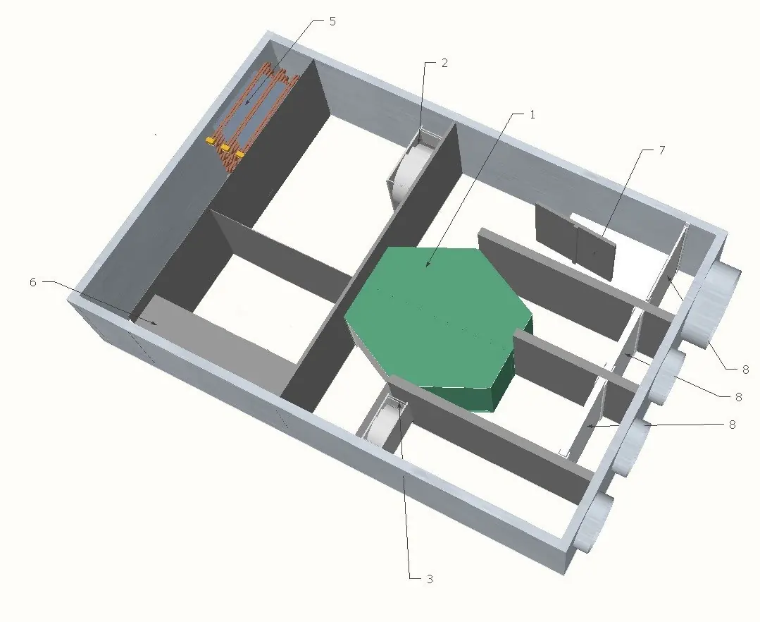
- Heat recovery core
- Inlet and exhaust fans
- Finned batteries
- Electrical cabinet
- Recirculating air damper
- Air filters
Installation
The unit can be installed on the ceiling or floor. Ensure the mounting surface is strong enough to support the weight and will not cause vibrations. Do not mount the unit with sides in direct contact with walls to avoid noise; use rubber or neoprene strips if necessary.
Condensate Drain Connection
Proper drainage is critical to prevent moisture buildup. Ensure a slope of at least 2% at the outlet pipe. A siphon must be installed and kept full of water, with dimensions H1 > 40mm and H2 > 40mm.
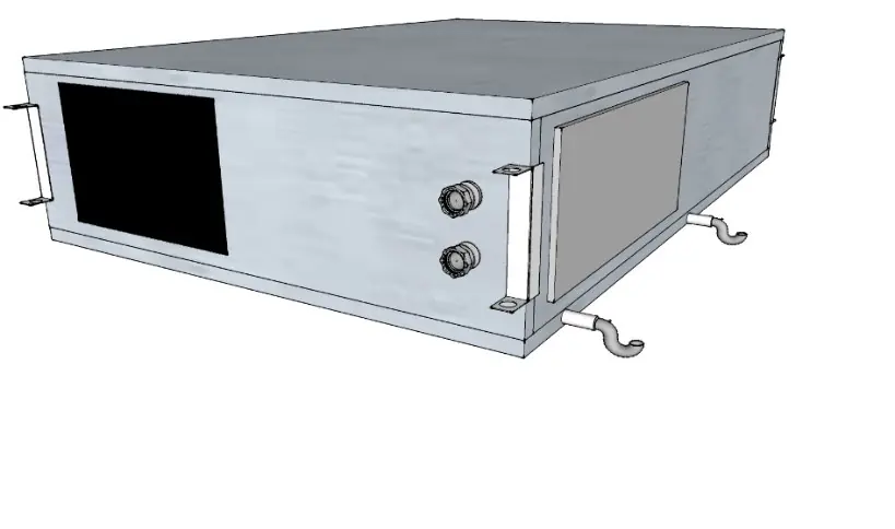
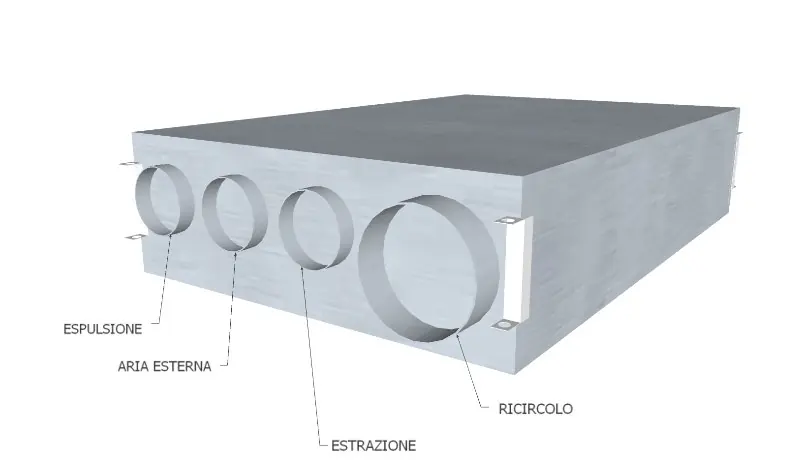
Aeraulic Connections
The unit features four circular rear connections and a rectangular front port. Refer to the unit's stickers for correct ducting. It is recommended to use at least 500mm of flexible piping to reduce vibration and noise.
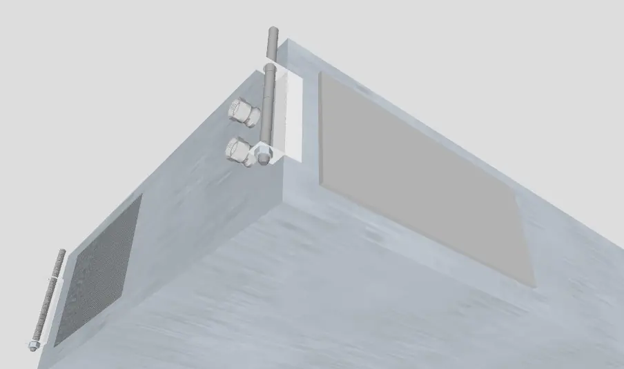
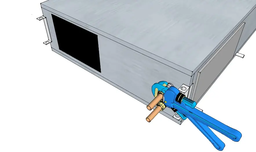
Plumbing Connections
The unit uses hydronic coils. Respect the IN (inlet) and OUT (outlet) markings. Ensure piping weight does not bear on the connections. Water quality must meet specific limits, including hardness < 10°F and pH between 7.5 and 9.
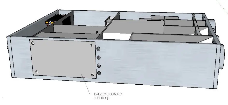
Electrical Connections
All electrical work must be done with the power disconnected. Use a dedicated power supply circuit and install a circuit breaker. The unit must be grounded. Wiring diagrams are provided in the manual for specific versions. For multi-unit control, use an RS485 network with shielded 2-wire cable, terminating the line with the provided 120 Ohm resistor.
Operation
The unit is controlled via a wall-mounted touch panel. Users can adjust fan speeds (Silent, Nominal, Maximum), change seasons (Winter/Summer), and set temperature or humidity set points. The 'Auto' function uses humidity and air quality sensors to regulate airflow.
Maintenance
Regular maintenance is required for optimal performance:
- Filters: Clean or replace periodically. Access via dedicated knobs.
- Heat Exchanger: Verify status during filter changes. Clean gently with a vacuum or low-pressure compressor.
- General Cleaning: Periodically clean fans, condensate drain, and internal walls. Do not remove balancing clips from fan blades.
Alarm
If an alarm occurs, an error code will appear on the display, or an LED on the electronic board will flash. Note the error code and contact your installer. Common issues include display failure (check power/fuse), low airflow (check filters/exchanger), or high noise (check panels/siphon).
Practical help
Common problems
Display OFF
Check power supply connection and replace the fuse on the black power connector.
Low or no air flow
Replace clogged filters, clean the heat exchanger, clean the fan, or check for clogged ducts.
High noise
Check for air leaks in panels, verify siphon connection, and ensure fan bearings are running correctly.
High vibrations
Verify panel integrity, ensure the lid is closed properly, and check that fan blades are balanced (do not remove balancing clips).
Condensation loss
Clean the condensate drain and ensure the unit is perfectly flat.
Before use
- Inspect unit for transport damage.
- Ensure installation location is frost-free and not overly humid.
- Verify 230V single-phase power supply is available.
- Install a siphon for the condensate drain (H1/H2 > 40mm).
- Ensure sufficient space around the unit for maintenance access.
- Check that the mounting surface can support the unit's weight.
Specs in practice
- Hardness < 10°F
- Maximum water hardness limit for the hydronic coils.
Images and diagrams
- Wiring diagrams illustrate connections for the remote display, chiller/boiler activation, and sensors.
- Condensate drain diagram shows the required siphon configuration.
- Multi-unit control diagram shows RS485 serial connection with termination resistor.
Model compatibility
- Compatible with Modbus RTU RS 485 home automation systems.
- Requires 230V single-phase power supply.
- Supports optional 2/3-way valves.

Manual page author
Emily Carter
User documentation editor
Prepares concise manual descriptions and highlights the most useful setup, operation, and maintenance information for readers.