HVAC / Ventilation Systems
User Manual for Vallox 110SE Ventilation Unit
Quick guide for the Vallox 110SE ventilation unit. Includes operating instructions, maintenance procedures, troubleshooting, and technical specifications.
Table of contents
Manual images
Click an image to enlargeQuick Guide
The Vallox 110SE is a low-energy ventilation unit with heat recovery. It is designed to operate continuously to maintain healthy indoor air quality. The unit features automatic demand-controlled ventilation when optional sensors are installed. To start the unit, connect the plug to the mains supply and select the desired ventilation power on the control panel.
Control Panel Operation
The control panel allows for full management of the ventilation system:
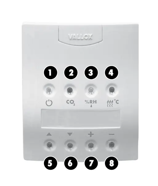
- Start button: Turns the unit on and off.
- Carbon dioxide adjustment: Toggles CO2-based ventilation control.
- Humidity adjustment: Toggles humidity-based ventilation control.
- Post-heating: Toggles the post-heating function.
- Navigation: Use scrolling buttons to move through menus and increase/decrease buttons to adjust values.
Ventilation Control Modes
The unit supports several control methods:
- Manual Control: Adjust fan speed (8 positions) directly via the control panel.
- Carbon Dioxide Control: Automatically adjusts fan speed to keep CO2 levels below the setpoint (factory setting 900 ppm).
- Humidity Control: Automatically adjusts fan speed based on humidity levels (automatic or fixed setpoint).
- Voltage Signal: Allows remote monitoring and control of fan speeds 0-8.
Special Functions
- Fireplace Switch: Stops the extract air fan for 15 minutes to create overpressure, making it easier to light a fireplace.
- Booster Switch: Increases fan speed to the maximum setting for 45 minutes.
- Winter Function: Automatically prevents the heat recovery cell from freezing by stopping the supply air fan or bypassing the cell.
- Week-clock Control: Allows programming of fan speeds and supply air temperatures for each hour of the week.
Maintenance
Regular maintenance is essential for optimal performance:
- Filters: Check cleanliness when the maintenance reminder alarm sounds. Replace filters in spring and autumn, or at least once a year.
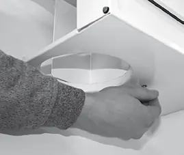
- Heat Recovery Cell: Check cleanliness every two years. If dirty, wash with a solution of water and washing-up liquid.
- Fans: Clean fans in place using compressed air or a brush. Do not remove balancing pieces.
- Condensing Water: Ensure the outlet in the bottom tank is not clogged, especially before the heating season.
Troubleshooting
If the unit displays error messages or malfunctions:
- Cold air: Check attic duct insulation and filter cleanliness.
- Sensor Faults: Messages like "Exh air sensor faulty" or "Sup. air sensor faulty" require contact with a maintenance company.
- Bus Fault: Check wiring for sensors and control panels.
- Fans not running: Check door switch and fuses (T800 mA).
Technical Data
- Electrical connection: 230 V, 50 Hz, 9.6 A.
- Weight: 60 kg.
- Degree of protection: IP34.
- Heat recovery: Cross-counter flow cell, >80% efficiency.
- Post-heating unit: 900 W, 3.9 A.
Installation
The unit must be mounted in a location where the temperature does not drop below +10 °C. Ensure the unit is mounted horizontally level. Avoid installing on hollow, echoing walls or bedroom walls to prevent sound conduction. Optional ceiling mounting plates and attic floor penetration plates are available for specific installation requirements.
Practical help
Common problems
Outdoor air coming to the dwelling is cold
Check insulation of attic ducts, cleanliness of filters and heat recovery cell, and ensure initial adjustment has been performed.
Maintenance reminder symbol displayed
Check cleanliness of filters and the unit. Clean or replace filters if needed and reset the reminder on the control panel.
Sensor faulty message (Exh, Sup, Ind, Out, Cell)
Contact a maintenance company; sensor mounting needs to be checked and the sensor replaced if necessary.
Bus fault message
Check wiring and connections for the carbon dioxide sensor, humidity sensor, or control panel.
Fans not running and no indicator light
Check door switch and fuses. The unit uses a T800 mA glass-tube fuse.
Before use
- Ensure the unit is mounted horizontally level.
- Check that the condensing water outlet is not clogged.
- Connect the plug to the mains supply.
- Verify that the control panel is connected and addressed correctly.
- Ensure the unit is installed in a location with no acoustic disturbance.
Specs in practice
- Electrical connection
- 230 V, 50 Hz, 9.6 A (plug).
- Degree of protection
- IP34, suitable for indoor installation.
- Heat recovery
- Cross-counter flow cell with >80% efficiency.
- Post-heating unit
- Standard electric unit, 900 W, 3.9 A.
Images and diagrams
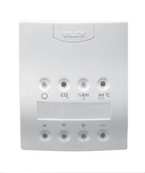
- Control panel layout shows buttons for power, CO2, humidity, post-heating, and navigation.
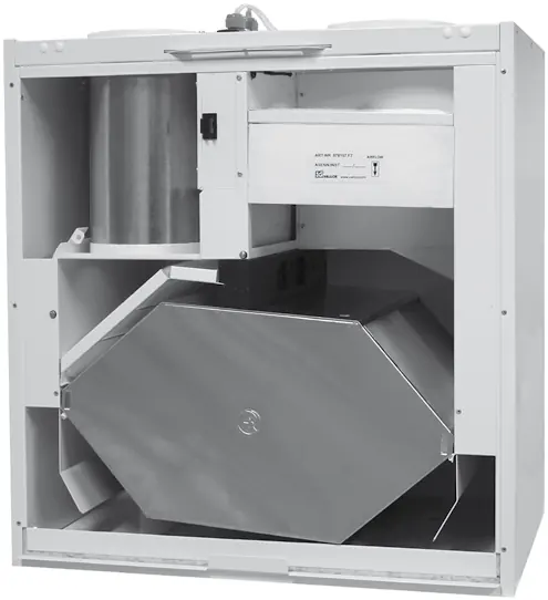
- Exploded view shows internal components like fans, filters, and heat recovery cell.
- Electrical connection diagram details wiring for sensors and control panels.
Model compatibility
- Compatible with optional CO2 and humidity sensors.
- Supports remote monitoring via voltage signal.
- Optional ceiling mounting plate and attic floor penetration plate available.

Manual page author
Emily Carter
User documentation editor
Prepares concise manual descriptions and highlights the most useful setup, operation, and maintenance information for readers.