Home Appliances / Hand Dryers
User Manual for Vent-Axia Lo-Carbon Revive Extractor Fan
Quick guide for the Vent-Axia Lo-Carbon Revive extractor fan. Includes installation, wiring diagrams, commissioning menu setup, maintenance, and troubleshooting steps.
Table of contents
Quick guide from the manual
The Vent-Axia Lo-Carbon Revive is a continuous or intermittent extract fan designed for kitchens, utility rooms, bathrooms, and toilets. Installation must be performed by a qualified person in accordance with current I.E.E. regulations. The fan features an LED display for configuration, adjustable boost settings, and humidity triggers. Always isolate the power supply before installation or maintenance.
Description
The Revive fan is a filterless unit capable of wall, window, or panel/ceiling mounting. It includes an integrated LED display for commissioning and monitoring. SELV models include a transformer that must be installed away from water spray and heat sources.
Installation
Siting: Do not install in areas with excessive grease, corrosive gases, or ambient temperatures outside the -5°C to 40°C range. For ducted fans, install a condensation trap and slope horizontal ducts slightly downwards away from the fan.
Mounting:
- Panel/Ceiling/Interior Wall: Cut a 105mm diameter hole.
- Exterior Wall: Cut a 117mm diameter hole and insert the wall sleeve, sloping it downwards.
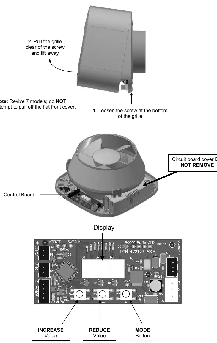
- Procedure: Loosen the screw at the bottom of the grille, remove the grille, mark screw centers, drill, plug, and screw the back plate into position. Ensure the impeller rotates freely before replacing the grille.
Wiring
The fan is a Class II double-insulated product and must not be earthed. Ensure the mains supply complies with the rating label. Use a local isolator switch with at least 3mm contact separation. Follow the specific wiring diagram (Fig 1-6) corresponding to your model and installation type (e.g., continuous trickle with boost, SELV models).
Setup and Commissioning
To configure the fan, remove the grille to access the control board. Do not isolate the power during configuration. Use the three buttons (+, -, X/Mode) to navigate the menu:
- Display rotation (r-n): Default or rotated 180 degrees.
- Intermittent (I-n/I-y): Enable or disable intermittent operation.
- Trickle mode (t09): Adjust airflow from 6 to 13 l/s.
- Kitchen/Bathroom mode (b-n/b-y): Sets default boost speeds.
- Ducted/Wall/Window (d-n/d-y): Adjusts for system pressure.
- Boost time (b15): Adjustable from 1 to 30 minutes.
- Humidity trigger (h60): Adjustable from 50% to 70% relative humidity.
- Comfort mode (c-n/c-y): Prevents nuisance boosting.
- Lock feature (unl/Loc): Prevents unauthorized adjustment.
Pull Cord and Data Logger
Pulling the cord activates boost 1, a second pull activates boost 2, and a third cancels the boost. Holding the Mode button for 5 seconds accesses the data logger, which displays total run time, energy usage, and humidity-boosted run time.
Servicing and Maintenance
The fan has sealed-for-life bearings and requires no lubrication. Periodically inspect the fan and clean the inlets and front face with a damp cloth to prevent dirt build-up. Always isolate the power supply before cleaning.
Troubleshooting
If the fan runs continuously in boost, check if the room is damp or recently decorated (may take 2 weeks to stabilize) or if the humidity set point is too low. If the fan fails to boost when humidity is high, increase the sensitivity by lowering the humidity set point. If water drips from a ceiling-mounted fan, install a condensation trap in the ducting.
Practical help
Common problems
Fan runs continuously in boost
Check if the room is damp or recently decorated (may take up to 2 weeks to stabilize) or if the humidity set point is set too low.
Fan does not boost when humidity is high
The humidity set point is likely set too high; adjust it to a lower setting in the commissioning menu.
Water dripping from ceiling-mounted fan
This is caused by condensation in the ducting. Install a condensation trap immediately after the fan.
Before use
- Ensure mains supply voltage, frequency, and phase match the rating label.
- Verify the installation is performed by a suitably qualified person.
- Ensure the local isolator switch has at least 3mm contact separation.
- Check that the impeller rotates freely after installation.
- Confirm the correct wiring diagram is selected for your specific model (SELV vs standard).
Specs in practice
- Humidity trigger
- The relative humidity level at which the fan triggers, adjustable from 50% to 70%.
- Trickle mode
- Continuous low-speed airflow, adjustable between 6 and 13 l/s.
Images and diagrams
- Fig 1-3: Wiring diagrams for standard 220-240V models.
- Fig 4-6: Wiring diagrams for SELV models requiring a transformer.
- Fig 7: Instructions for removing the grille to access the control board and buttons.
Model compatibility
- SELV models require a transformer and must not be installed in shower enclosures.
- The fan is Class II double insulated and must not be earthed.
- Not suitable for environments with excessive grease or corrosive gases.

Manual page author
Michael Turner
Technical manual editor
Reviews PDF manuals for structure, safety notes, and practical product details so readers can find the right information quickly.