Industrial / Electrical
User Manual for Intellinet 562201 5-Port 10G Ethernet Switch
Quick guide for the Intellinet 562201 5-Port 10G Ethernet Switch. Includes installation instructions, LED status indicators, and connection guidelines.
Table of contents
Manual images
Click an image to enlargeQuick Guide
This manual provides instructions for the Intellinet 5-Port 10G Ethernet Switch (Model 562201). It covers the setup, connection, and LED status interpretation required for proper operation.
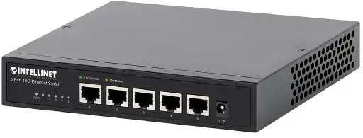
Connections and Indicators
The switch features LED indicators to help monitor the device status and network connections.
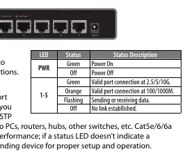
- PWR LED: Green indicates the device is powered on; Off indicates power is off.
- Ports 1-5 LEDs: Green indicates a valid connection at 2.5/5/10G. Orange indicates a valid connection at 100/1000M. Flashing indicates data transmission. Off indicates no link established.
All RJ45 ports support Auto-MDI/MDI-X functionality, allowing the use of both straight and crossover UTP/STP cables to connect to PCs, routers, hubs, and other switches. Cat5e/6/6a cables are recommended for optimal performance.
Installation
To ensure proper operation and longevity of the switch, follow these installation guidelines:
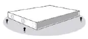
- Place the switch on a level surface capable of supporting its weight.
- Maintain at least 25 mm (approx. 1 inch) of clearance around the device for adequate ventilation.
- Keep the switch away from sources of electrical noise, such as radios, transmitters, and broadband amplifiers.
- Ensure the switch is within 100 m (approx. 328 feet) of the network devices it is connected to.
- Attach the included rubber feet to the bottom corners of the switch to increase stability.
Use the included power adapter to connect the device to the DC IN port and verify that the PWR LED is lit.
Regulatory and Disposal
This device complies with FCC Class A limits for commercial environments. It also adheres to EU Directive 2012/19/EU regarding the disposal of electrical and electronic equipment (WEEE). Do not dispose of this product with unsorted household waste; return it to a designated recycling point.
Manufacturer information
Intellinet Network Solutions
Practical help
Common problems
LED does not indicate link or activity
Check the connected device for proper setup, configuration, and power.
No power
Ensure the included power adapter is securely connected to the DC IN port and a functioning power outlet.
Before use
- Ensure the surface is level and can support the switch weight.
- Provide at least 25 mm of clearance for ventilation.
- Keep away from sources of electrical noise (radios, transmitters, etc.).
- Ensure network devices are within 100 m of the switch.
- Attach the included rubber feet to the bottom corners.
Specs in practice
- Auto-MDI/MDI-X
- Allows the use of both straight and crossover UTP/STP cables for network connections.
Images and diagrams
- The LED table on page 2 provides a quick reference for interpreting the PWR and Port 1-5 status lights.
Model compatibility
- Compatible with Cat5e, Cat6, and Cat6a UTP/STP cables.
- Supports connection to PCs, routers, hubs, and other switches.

Manual page author
Michael Turner
Technical manual editor
Reviews PDF manuals for structure, safety notes, and practical product details so readers can find the right information quickly.