Industrial / Electrical
User Manual for Intellinet 562324 Outdoor 10-Port PoE+ Switch
Quick setup guide for the Intellinet 562324 Outdoor 10-Port L2+ Fully Managed PoE+ Switch. Includes installation, wiring, LED status, and safety instructions.
Table of contents
Manual images
Click an image to enlargeQuick guide from the manual
This guide provides the essential steps to install and operate the Intellinet 562324 Outdoor 10-Port L2+ Fully Managed PoE+ Switch. The device features eight 10/100/1000Mbps PoE+ ports and two SFP uplink ports, housed in an IP65-rated rainproof ABS plastic shell suitable for wall or pole mounting.
Placement and Mounting
For optimal performance and safety, follow these placement guidelines:
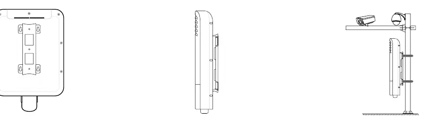
- Ensure the mounting surface can support the weight of the switch.
- Maintain a minimum clearance of 25 mm (approx. 1 inch) on the top and sides to ensure adequate ventilation.
- Install the device away from sources of electrical noise, such as radios, transmitters, and broadband amplifiers.
- Ensure the device is within 100 meters (approx. 328 feet) of the network devices it will be connected to.
- Use the mounting brackets on the back of the unit for wall or pole installation.
Connections
To connect your network devices:
- Open the bottom cover to access the ports.
- Secure the cover tightly after connecting cables to maintain the IP65 waterproof and dustproof rating.
- The switch supports Auto-MDI/MDI-X, allowing the use of straight or crossover UTP/STP cables.
- Cat5e/6/6a/8.x cables are recommended for optimal performance.
- Ports 1-8 are PSE (Power Sourcing Equipment) ports compliant with IEEE 802.3af/at, suitable for PoE devices like VoIP phones and network cameras. Non-PoE Ethernet devices can also be connected to these ports.
Power Supply Wiring
Warning: Ensure all power is disconnected before beginning installation.
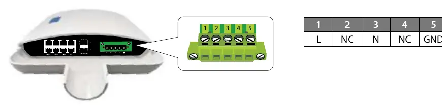
- The internal power supply supports input voltages of 100-240VAC, 50/60Hz.
- Use wire with a gauge between 12-24 AWG for the terminal block.
- Loosen the screws on the terminal block.
- Insert the bare power-supply wires into the appropriate slots: L (Live) to slot 1, N (Neutral) to slot 3, and Ground to slot 5.
- Tighten the screws to secure the wires.
- Install the block into the device and tighten the screws.
- Observe polarity markings on the interface to avoid connection errors.
LED Indicators
Monitor the switch status using the front panel LEDs:
- PWR: On indicates power is supplied; Off indicates no power.
- LINK (1-8): Green indicates a network link; Flashing indicates data transmission; Off indicates no link.
- PoE (1-8): Blue indicates the port is supplying power to a connected device; Off indicates no power delivery.
- UPLINK (9-10): On indicates a device is connected; Off indicates no device.
Safety and Maintenance
- Do not attempt to open or repair the device yourself, as this voids the warranty and poses safety risks.
- Disconnect power before cleaning or servicing.
- Use only a dry cloth for cleaning; do not immerse or spray liquids on the device.
- If the device is dropped, punctured, or exposed to liquid, discontinue use and contact support.
Manufacturer information
Intellinet Network Solutions
Practical help
Common problems
No link or activity LED
Check the connected device for proper setup, configuration, and power.
PoE device not receiving power
Ensure the device is connected to ports 1-8 and is a PoE-compatible device.
No power to the switch
Verify the terminal block wiring (L, N, Ground) and ensure the input voltage is within 100-240VAC.
Before use
- Ensure the mounting surface can support the switch weight.
- Maintain at least 25mm clearance for ventilation.
- Keep away from electrical noise sources (radios, transmitters).
- Verify network cable distance is within 100m.
- Ensure power is disconnected before wiring the terminal block.
Specs in practice
- Auto-MDI/MDI-X
- Allows use of both straight and crossover Ethernet cables.
Images and diagrams
- Terminal block wiring: Connect Live (L) to pin 1, Neutral (N) to pin 3, and Ground to pin 5.
Model compatibility
- Ports 1-8: IEEE 802.3af/at compliant PoE ports.
- Ports 9-10: SFP Uplink ports.

Manual page author
Michael Turner
Technical manual editor
Reviews PDF manuals for structure, safety notes, and practical product details so readers can find the right information quickly.