Furniture / Tables & Desks
Assembly Instructions for Invicta Interior 130cm Coffee Table
Quick assembly guide for the Invicta Interior 130cm coffee table (Article 43344). Includes a parts list, step-by-step assembly instructions, and contact information for support.
Table of contents
Quick Assembly Guide
This document provides assembly instructions for the Invicta Interior 130cm coffee table (Article No. 43344). Before beginning, ensure you have all the parts listed below. It is recommended to assemble the table on a soft surface, such as a rug or the packaging cardboard, to prevent scratches or damage to the wood and glass components.
Parts List
- A1: Side frame (x2)
- A2: Crossbar (x1)
- A3: Support beam (x2)
- A4: Top frame (x2)
- B1: M8*16 mm screw (x10)
- B2: M8*25 mm screw (x4)
- C: Washer (x14)
- D: M5 Allen key (x1)
Assembly Steps
Step 1
Connect the side frames (A1) to the crossbar (A2) using screws (B1) and washers (C). Tighten using the provided Allen key (D).
Step 2
Attach the support beams (A3) to the structure created in Step 1 using screws (B1) and washers (C).
Step 3
Attach the top frames (A4) to the assembly using screws (B2) and washers (C). Ensure all connections are secure before placing the glass top onto the frame.
Customer Support
If you have any questions regarding this article, please contact your dealer directly. Manufacturer: Invicta Interior GmbH & Co KG, Kirchenweg 8, 24568 Nützen. Tel.: 04101 - 80 40 615. Email: [email protected].
Manufacturer information
Invicta Interior GmbH & Co. KG
Practical help
Common problems
Missing parts or hardware
Contact your dealer directly for assistance with missing components.
Difficulty tightening screws
Ensure you are using the correct screw type (B1 vs B2) as specified in the assembly steps and that the washer (C) is placed correctly.
Before use
- Verify all parts (A1-A4) and hardware (B1, B2, C, D) are present.
- Prepare a soft, clean surface for assembly.
- Ensure you have the M5 Allen key (D) ready.
- Check that all screws are tightened securely before placing the glass top.
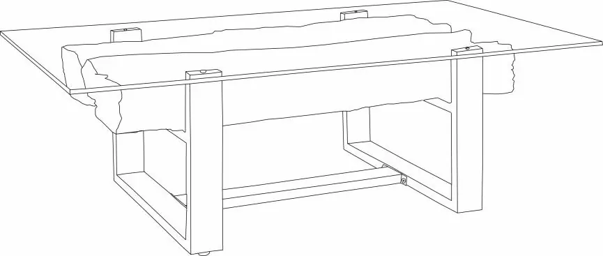
Images and diagrams
- The diagram illustrates the sequential assembly of the base frame, support beams, and top frame.
- Arrows indicate the specific connection points for each screw and component.
Model compatibility
- This product is intended for indoor use.

Manual page author
David Miller
Documentation analyst
Organizes user manual content into clear summaries, with attention to model details, product context, and everyday usability.