HVAC / Parts & Accessories
Reznor Gas Conversion Kit Installation Guide for Unit Heaters
Comprehensive installation guide for Reznor gas conversion kits. Includes step-by-step instructions for regulator spring installation, air restrictor plate adjustment, burner orifice replacement, and manifold pressure settings for UDBP...
Table of contents
Manual images
Click an image to enlargeQuick guide from the manual
This document provides instructions for converting Reznor unit heaters between natural gas and propane. It covers kit selection, component installation, and pressure adjustment. Warning: Gas conversion must be performed by a qualified service person. Improper installation can result in fire, explosion, injury, or death.
Kit selection
Before beginning, identify your heater model and unit size. Refer to Table 1 (Natural Gas to Propane) or Table 2 (Propane to Natural Gas) to select the correct kit components. Ensure you have the correct spring kit, burner orifices, and air restrictor plate for your specific unit size and gas valve type.
Installation steps
Follow these steps to perform the conversion:
- Shut down: Turn off the gas supply at the shutoff valve and disconnect electrical power. Open the control access panel.
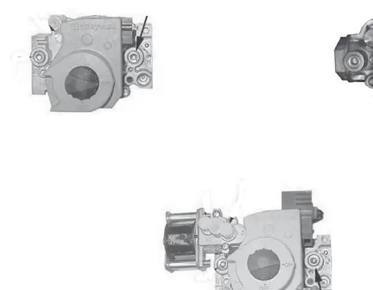
- Regulator spring kit: Install the regulator spring kit corresponding to your gas valve. Do not interchange kits. Follow the gas valve manufacturer's instructions included with the spring kit.
- Air restrictor plate: Install or remove the air restrictor plate based on the fuel type and unit size. For propane conversion on specific sizes, the plate must be installed; for natural gas, it must be removed. Use pliers to bend or unbend the tabs on the venturi tube to secure or release the plate.
- Burner orifice: Replace the burner orifice with the size specified in Table 3. Do not attempt to drill the orifice; use only factory-supplied parts.
- High elevation: If the heater is operated at an elevation above 6,000 feet (1,830 meters), a high-elevation pressure switch must be installed.
Manifold pressure adjustment
After installing the conversion kit, you must adjust the manifold pressure:
- Connect a manometer to the 1/8-inch output pressure tap on the gas valve.
- Turn the gas valve to ON and operate the heater.
- Adjust the regulator screw (IN to increase, OUT to decrease) until the pressure matches the values in Table 4 for your elevation.
- Caution: Do not bottom out the regulator screw, as this can cause unregulated pressure and heat exchanger failure.
- Perform a leak test on all connections using a commercial leak-detecting fluid or soap solution.
Safety and maintenance
Always verify the input rate on the heater rating plate after conversion. If the unit is adjusted for high-elevation operation, the input rate will be affected. Ensure the high-elevation adjustment label is filled out and affixed to the heater access panel if required.
Practical help
Common problems
Incomplete combustion
Ensure the installation permits proper combustion air supply and that the vent system is operating correctly.
Gas leak detected during test
Tighten the connection. If the leak persists, replace the part.
Incorrect manifold pressure
Adjust the regulator screw according to Table 4. Do not bottom out the screw.
Before use
- Verify heater model and kit compatibility using Table 1 or Table 2.
- Turn off gas supply at the shutoff valve.
- Turn off electrical power.
- Ensure you have a manometer for pressure adjustment.
- Check installation elevation; if >6,000 ft, install high-elevation pressure switch.
- Have a permanent marker ready to fill out the high-elevation adjustment label.
Specs in practice
- Manifold Pressure
- Gas pressure at the valve outlet. Must not exceed 3.5 IN WC for natural gas or 10 IN WC for propane.
- Air Restrictor Plate
- A component used to regulate combustion air. Must be installed or removed based on fuel type and unit size.
Images and diagrams
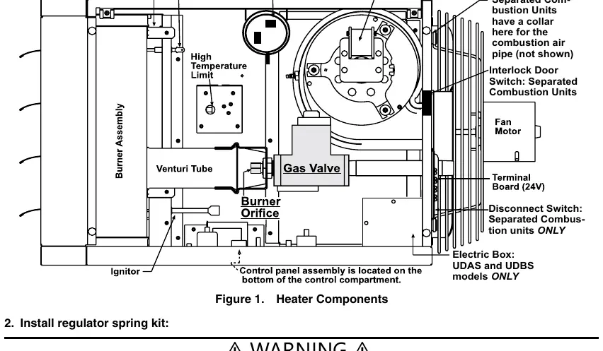
- Figure 1: Shows the location of heater components including the burner assembly, gas valve, and pressure switch.
- Figure 2: Illustrates how to install or remove the air restrictor plate on the venturi tube and replace the burner orifice.
- Figure 3: Identifies the regulator screw, inlet pressure tap, and outlet pressure tap on single-stage and two-stage gas valves.
Model compatibility
- Regulator spring kits are not interchangeable; use only the kit designated for your specific gas valve.
- Air restrictor plate requirements vary by unit size and fuel type; refer to the installation instructions carefully.
- High-elevation pressure switch is required for elevations above 6,000 feet.

Manual page author
David Miller
Documentation analyst
Organizes user manual content into clear summaries, with attention to model details, product context, and everyday usability.