HVAC / Parts & Accessories
Gas Conversion Kit Installation Guide for Reznor Unit Heaters
Professional installation guide for Reznor gas conversion kits. Includes step-by-step instructions for converting unit heaters between natural gas and propane, including spring kit installation, air restrictor plate adjustment, and...
Table of contents
Manual images
Click an image to enlargeQuick guide from the manual
This document provides instructions for converting Reznor unit heaters between natural gas and propane. It is intended for qualified service personnel only. Improper installation can result in fire, explosion, or carbon monoxide poisoning.
Safety Information
DANGER: Failure to follow safety warnings can result in serious injury, death, or property damage. Installation and service must be performed by a qualified installer, service agency, or the gas supplier.
- If you smell gas, do not try to light any appliance, do not touch electrical switches, and leave the building immediately.
- Ensure the installation permits the burner to receive the proper supply of combustion air to prevent incomplete combustion.
- Maintain the vent or vent/combustion air system in structurally sound condition.
Kit Selection
Each conversion kit includes specific spring kits and burner orifices for multiple unit sizes. Refer to Table 1 (Natural Gas to Propane) or Table 2 (Propane to Natural Gas) in the manual to select the correct components based on your unit size and model.
Installation Procedure
- Remove gas supply and electrical power: Turn off the gas supply at the shutoff valve and turn off electrical power. Open the control access panel.
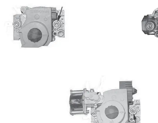
- Install regulator spring kit: Select the spring kit that corresponds with the gas valve on the heater. Install according to the gas valve manufacturer's instructions.
- Air restrictor plate: Install or remove the air restrictor plate based on the unit size and gas type. Use pliers to bend or unbend tabs to secure the plate on the venturi tube.
- Replace burner orifice: Select the replacement burner orifice according to Table 3. Do not attempt to drill the orifice.
- High-elevation pressure switch: If the heater is operated at an elevation greater than 6,000 feet (1,830 meters), a high-elevation pressure switch must be installed.
- Leak test: Check all connections for gas leaks using commercial leak-detecting fluid or a soap and water solution.
Manifold Pressure Adjustment
After installing the new regulator spring kit, you must adjust the spring for the correct manifold pressure while the heater is in operation.
- Warning: Manifold gas pressure must never exceed 3.5 IN WC for natural gas or 10 IN WC for propane.
- Use a water column manometer to measure pressure.
- Connect the manometer to the 1/8-inch output pressure tap on the valve.
- Adjust the regulator screw (clockwise to increase, counterclockwise to decrease) according to the values in Table 4.
- For two-stage valves, adjust both high-fire and low-fire settings.
Practical help
Common problems
Gas leaks detected during testing
Tighten the connection. If the leak persists, replace the part.
Incomplete combustion
Ensure the installation permits proper supply of combustion air and that the vent system is operating correctly.
Incorrect manifold pressure
Adjust the regulator screw on the gas valve while the heater is in operation, ensuring it does not exceed 3.5 IN WC (Natural Gas) or 10 IN WC (Propane).
Before use
- Verify the conversion kit is correct for the specific unit size and model.
- Ensure a qualified service person is performing the installation.
- Shut off gas supply and electrical power before starting.
- Have a manometer (fluid-filled gauge) ready for pressure adjustment.
- Check installation elevation to determine if a high-elevation pressure switch is required.
Specs in practice
- Manifold Pressure (Natural Gas)
- Must not exceed 3.5 IN WC.
- Manifold Pressure (Propane)
- Must not exceed 10 IN WC.
- High Elevation
- Elevations >6,000 feet (1,830 meters) require a high-elevation pressure switch.
Images and diagrams
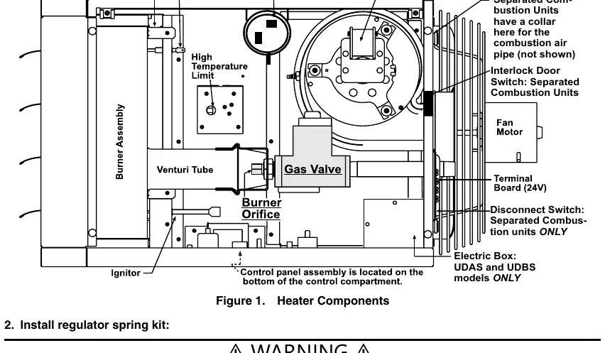
- Figure 1: Shows the location of heater components including the gas valve, burner orifice, and venturi tube.
- Figure 2: Illustrates the installation and removal of the air restrictor plate and burner orifice.
- Figure 3: Details the gas valve adjustment points, including regulator screws and pressure taps.
Model compatibility
- Kits are specific to unit sizes and gas valve types (single-stage or two-stage).
- Regulator spring kits are not interchangeable.
- Compatible with Reznor models UDBP, UBX, UDBS, UBZ, UDAP, UDX, UDAS, and UDZ.

Manual page author
David Miller
Documentation analyst
Organizes user manual content into clear summaries, with attention to model details, product context, and everyday usability.