Power / Uninterruptible Power Supplies
Honeywell 10260S Series Actuators MOV Assembly Kit Installation Instructions
Installation guide for the Honeywell 10260S Series Actuators MOV Assembly Kit. Includes step-by-step procedures for installing the 51500671-503 and 51500671-504 kits, tool requirements, and safety precautions.
Table of contents
Manual images
Click an image to enlargeImportant Information
This document provides instructions for adding or replacing the Metal Oxide Varistor (MOV) assembly on 10260S Series Actuators. Before beginning, ensure you have the correct kit for your actuator's input voltage: Part # 51500671-503 for 120 Vac input or Part # 51500671-504 for 230 Vac input.
Safety Precautions
- Disconnect Power: Always disconnect AC power to the actuator before accessing internal components.
- Electrostatic Discharge (ESD): When working with Printed Wiring Assemblies (PWAs), wear a grounded wrist strap to prevent damage from electrostatic discharge.
Tools Needed
- Medium Flat-blade screwdriver
- Medium Phillips screwdriver
- Small needle-nosed pliers
Installation Procedure
- Remove AC power to the actuator.
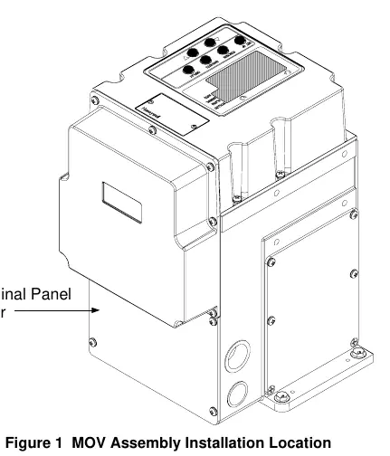
- Remove the four screws and the terminal cover from the side of the actuator case.
- Locate terminals TB1-1 (marked L) and TB1-2 (marked N) and the ground screw on the actuator terminal block.
- Remove the screws from terminals TB1-1, TB1-2, and the ground screw location.
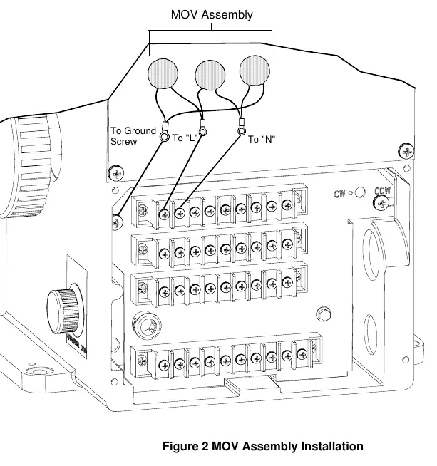
- Install the MOV assembly. Attach the larger size lug terminal to the ground screw on the terminal panel. Attach the remaining lug terminals to TB1-1 and TB1-2 on the actuator terminal panel.
- Install a new gasket and the terminal panel cover. Secure the cover to the actuator using the four screws.
- Reapply AC power to the actuator.
- Verify the actuator configuration and check for correct operation.
- Return the actuator to service.
Manufacturer information
Honeywell International Inc.
Practical help
Common problems
Incorrect kit selection
Ensure you are using Part # 51500671-503 for 120 Vac input or Part # 51500671-504 for 230 Vac input.
Before use
- Verify the correct MOV assembly kit for your actuator input voltage.
- Ensure AC power to the actuator is completely disconnected.
- Prepare a medium flat-blade screwdriver, medium Phillips screwdriver, and small needle-nosed pliers.
- Use a grounded wrist strap to protect against electrostatic discharge.
Specs in practice
- 51500671-503
- MOV assembly kit designed for 120 Vac input.
- 51500671-504
- MOV assembly kit designed for 230 Vac input.
Images and diagrams
- Figure 1 illustrates the location of the terminal panel cover on the side of the actuator.
- Figure 2 shows the wiring connections for the MOV assembly, specifically identifying the ground screw, terminal L, and terminal N.
Model compatibility
- These instructions apply specifically to 10260S Series Actuators.
- The MOV assembly is required for 10260S actuators that must conform to CE requirements.

Manual page author
David Miller
Documentation analyst
Organizes user manual content into clear summaries, with attention to model details, product context, and everyday usability.