HVAC / Water Heaters
Rinnai PC Board Replacement Instructions
A comprehensive guide for replacing the PC Board in Rinnai SENSEI RX/CX tankless water heaters. Includes procedures for data collection, board installation, parameter configuration, gas valve calibration, and combustion verification.
Table of contents
Manual images
Click an image to enlargeImportant Information
This document provides instructions for replacing the PC Board in Rinnai SENSEI RX/CX Condensing Tankless Water Heaters. This procedure involves sensitive electronic components and gas valve calibration. Ensure you have the necessary tools and follow all safety warnings to prevent electrocution or gas leaks.
Preparation and Tools
Before beginning, ensure you have the following:
- Phillips head screwdriver
- Smart device (smartphone or tablet) with Bluetooth 4.0 or newer
- Access to the Tankless Water Heater Installation and Operation Manual
- Gas analyzer (for final verification)
Step 1: Data Collection
Before removing the old board, you must collect existing performance data:
- Press and hold the down arrow button on the controller.
- While holding the down arrow, press and hold the On/Off button for 2 seconds until 01 appears.
- Use the up and down arrows to scroll through the performance data (Combustion Hours and Combustion Cycles).
- Record these values for reference.
Step 2: Install PC Board and Data Transfer
- Remove the water heater front panel.
- Turn off and disconnect 120 V power supply.
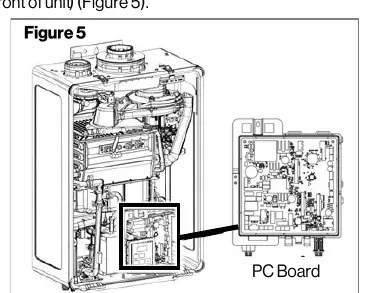
- Locate the PC Board in the lower front of the unit.
- Remove the screw at the top of the PC Board to remove the original board.
- Disconnect all wire harnesses from the original board.
- Install the new PC Board and secure it with the screw.
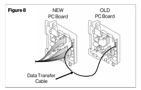
- Connect the provided Data Transfer Cable to the blue connector on both the new and original PC Boards.
- Reconnect power. When 't' appears on the display, press the 'A' button on the new board for 1 second.
- If successful, the controller will display 'PRS'. If 'bAd' appears, disconnect power and retry.
Step 3: Parameter Settings
After data transfer, you must configure the parameters. This can be done via the Rinnai Central app (recommended) or manually using the integrated controller. Refer to the Parameter Settings Table in the manual to select the correct settings for your specific installation (e.g., High Altitude, Recirculation, Gas Type, Indoor/Outdoor).
Step 4: Enter Gas Valve Parameters
The water heater will display an error code until gas valve values are entered. You can use the Rinnai Central app or the integrated controller:
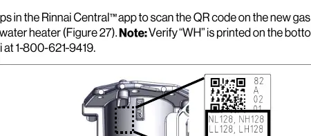
- Locate the gas valve label on the unit (verify 'WH' is printed on the label).
- Using the controller, press the 'B' button for 1 second.
- Press 'B' twice to confirm 'Adj' appears.
- Use the 'A' button to confirm 'nL' (natural gas low) or 'LL' (propane low).
- Use arrow buttons to match the displayed value to the value on the gas valve label.
- Repeat for 'nH'/'LH' (high settings) and 'HS' (hysteresis).
- Press 'A' to show entered values, then 'B' for 2 seconds to complete.
Step 5: Verification
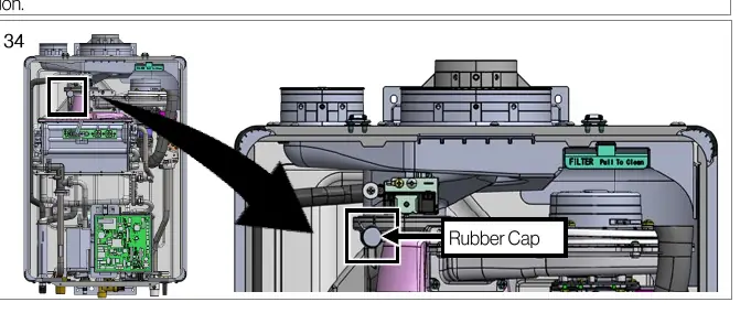
- Remove the rubber cap and insert a gas analyzer probe.
- Start the unit and run for at least 5 minutes.
- Measure CO2 and O2 concentrations.
- Ensure values are within the specified ranges (NG: 7.0-11.0% CO2; LPG: 7.9-11.9% CO2).
- Reinstall the rubber cap and front panel.
Practical help
Common problems
Data transfer unsuccessful (display shows 'bAd' or is blank)
Disconnect power and the data transfer cable, then repeat the data transfer steps.
Error code 21
This may occur when changing gas settings. Complete 'Step 3: Enter Gas Valve Parameters' to resolve.
Before use
- Phillips head screwdriver
- Smart device with Bluetooth 4.0+ for Rinnai Central app
- Gas analyzer for combustion verification
- Access to the main Installation and Operation Manual
- Verify 'WH' is printed on the gas valve label
Images and diagrams
- Figure 5: Location of the PC Board in the lower front of the unit.
- Figure 8: Connection of the Data Transfer Cable between the new and old PC boards.
- Figure 27: Location of the gas valve label required for parameter verification.
- Figure 34: Location of the rubber cap for gas analyzer probe insertion.
Model compatibility
- Compatible with SENSEI RX/CX Condensing Tankless Water Heaters.
- Kit 105002028 is for Residential models.
- Kit 105002029 is for Commercial models.

Manual page author
Emily Carter
User documentation editor
Prepares concise manual descriptions and highlights the most useful setup, operation, and maintenance information for readers.