Tools / Welding Equipment
Operator's Manual for Lincoln Electric SPRINTER 160S / 180S Welding Machine
Quick guide for the Lincoln Electric SPRINTER 160S and 180S welding machines. Includes setup, SMAW/GTAW operation, safety warnings, maintenance, and troubleshooting.
Table of contents
Manual images
Click an image to enlargeQuick Guide and Safety Information
The Lincoln Electric SPRINTER 160S and 180S are professional welding machines designed for SMAW (Stick) and GTAW (Lift TIG) processes. Before operating, ensure you have read the full safety section. Always wear appropriate personal protective equipment (PPE), including a welding helmet with the correct filter, flame-resistant clothing, and gloves. Ensure the work area is well-ventilated and free of fire hazards.
Installation and Setup
Location: Place the machine on a stable surface with an incline no greater than 15 degrees. Ensure free air circulation around the vents; do not cover the machine. Keep the area dry and away from rain or snow.
Input Connection: The machine requires a 120V/230V 50/60Hz power supply. Connection must be performed by a qualified electrician. If using a generator, it should have a recommended power of 10 kVA.
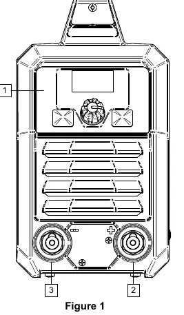
Output Connections: Refer to the front panel sockets. Connect the electrode holder and work lead according to the required polarity (DC+ or DC-) as specified in the welding process instructions.
Controls and Operation
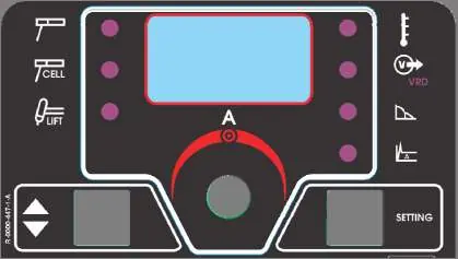
The front panel features a digital display and control knobs for adjusting welding parameters. Use the left button to select the process (SMAW or GTAW) and the right button to select parameters like Hot Start or Arc Force. The central knob allows for adjustment and confirmation of values.
SMAW (Stick) Welding: Ensure the machine is off before connecting leads. Determine polarity based on electrode data, connect the work lead and electrode holder, then power on the machine to set parameters.
GTAW (Lift TIG) Welding: Requires a separate TIG torch (not included). Connect the torch to the negative output socket and the work lead to the positive socket. Use the Lift TIG method for arc ignition.
Maintenance
Routine Maintenance (Everyday): Inspect insulation on all cables and leads. Replace damaged cables immediately. Clean the welding gun nozzle of spatters and ensure the cooling fan is operational and airflow slots are clean.
Periodic Maintenance (Every 200 hours/Year): Clean the machine internally using dry, low-pressure air to remove dust. Check and tighten all weld terminals.
Troubleshooting
If the machine fails to operate, check the power switch and input voltage. If the yellow thermal overload light is on, the machine has exceeded its duty cycle; allow it to cool. For arc issues in TIG mode, check tungsten electrode preparation, gas flow, and cable connections.
Practical help
Common problems
Machine not working (no output, no fan)
Ensure the power switch is in the ON position, the machine is plugged in, and check for blown input fuses.
Fan runs but no output (Yellow light on)
The machine has exceeded the recommended duty cycle. Allow the unit to cool until the yellow light turns off.
Arc flutters during TIG welding
Check for contaminated gas, leaks in the gas line, or improper tungsten electrode preparation. Ensure gas flow is sufficient.
Stick electrode sticks in the weld puddle
The weld current may be set too low. Increase the current control setting or use a smaller diameter electrode.
Before use
- Check packaging and equipment for shipping damage.
- Verify input voltage matches the rating plate.
- Ensure the machine is on a stable surface (incline < 15 degrees).
- Check all cable insulation for damage.
- Ensure adequate ventilation and clear air vents.
- Verify proper grounding of the work piece.
Specs in practice
- GTAW (Lift TIG)
- Gas Tungsten Arc Welding using the Lift TIG ignition method.
Images and diagrams
- Figure 1: Front panel showing output sockets and controls.
- Figure 2: Rear panel showing power switch and input cord.
- Figure 3: User interface display, buttons, and LED indicators.
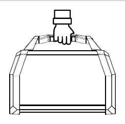
- Figure 4: Transport handle usage.
Model compatibility
- Requires 120V/230V 50/60Hz input.
- Generator power recommended: 10 kVA.
- Class A equipment intended for industrial use only.

Manual page author
Michael Turner
Technical manual editor
Reviews PDF manuals for structure, safety notes, and practical product details so readers can find the right information quickly.