Industrial / Vacuum Cleaners
Draper 160A MIG Welder User Manual
Quick guide for the Draper 160A MIG Welder (71095). Includes setup, wire installation, welding principles, maintenance, and troubleshooting steps.
Table of contents
Manual images
Click an image to enlargeQuick guide from the manual
This manual provides essential instructions for the safe operation and maintenance of the Draper 160A MIG Welder. Before starting, ensure you have a suitable 16A power supply and that you are wearing appropriate personal protective equipment (PPE), including welding eye/face protection, gloves, and flame-retardant clothing. Always ensure the machine is properly earthed and the work area is clear of flammable materials.
Technical description
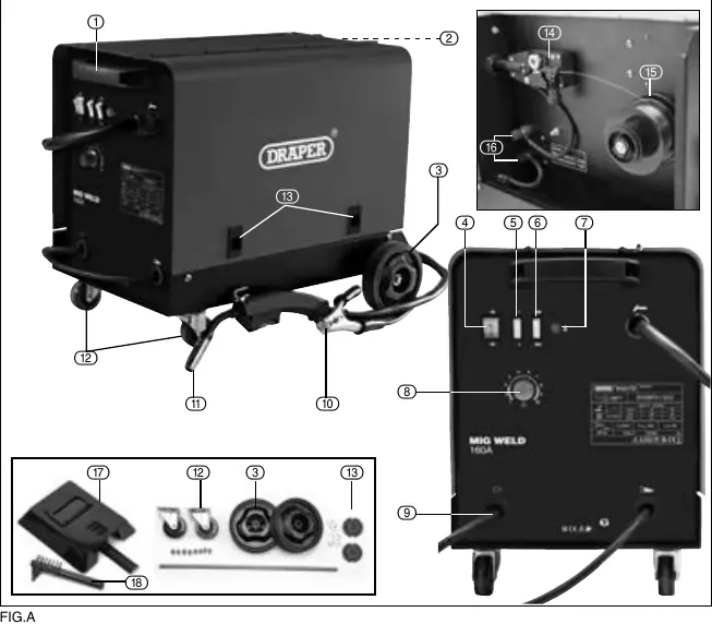
The welder features a transport handle, rear wheels, and front castors for mobility. Key components include the ON/OFF switch, power switches (1, 2, Max, Min), wire feed speed control, and the MIG torch connection. The wire feed assembly and spool hub are located inside the side panel.
Assembly and setup
Fitting the wheels: Attach the front castor wheels using the 8 provided screws. Slide the axle through the loops, fit the circlips, wheels, and washers as described in the assembly section.
Installing the filler wire:
- Open the side panel.
- Unscrew the large plastic ring, place the 1kg wire spool on the hub, and refit the ring.
- Feed the wire towards the wire drive unit.
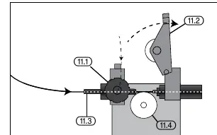
- Ensure the wire sits in the correct groove on the drive roller for the wire gauge.
- Pass the wire through the guide and into the torch liner before closing the tension arm.
Operation
Welding current and wire speed: Use the current regulation switches (Min +1, Min +2, Max +1, Max +2) to adjust power based on material thickness. Wire speed must be adjusted in conjunction with the current; if the wire hits the metal, it is too fast; if it clogs the tip, it is too slow.
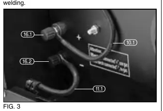
Gas/Gasless setup: For gasless (flux-cored) welding, attach the earth clamp to the positive terminal and the torch connector to the negative terminal. Reverse these connections for gas welding.
Welding principles
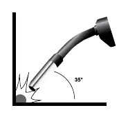
For a quality weld, ensure the area is clean of grease, dirt, and rust. Position the torch at approximately 35° vertically and 75° horizontally, keeping it up to 20mm from the join. Ensure the gas shroud and wire feed tip remain clean of spatter.
Maintenance and troubleshooting
Regularly clean the contact tip and gas shroud with an iron brush. Check the torch cable and ground connections. If the welder stops working, it may have overheated; allow it to cool down. If the wire is not feeding, check for a dirty contact tip, incorrect pulley tension, or a damaged torch liner.
Manufacturer information
Draper Tools
Practical help
Common problems
Wire not feeding despite pulley turning
Clean the contact tip, loosen the pulley if too tight, or increase clamping pressure if too loose.
Interrupted or disruptive wire supply
Replace damaged/burnt contact tip or clean/replace the torch liner.
Electric arc turned off
Tighten earth clamp connection, clean/replace nozzles, or ensure the contact tip is tight.
Welder stops working after long operation
The thermal protection has activated. Turn off and let the welder cool down.
Before use
- Ensure power supply is 230V AC with a 16A fuse.
- Wear appropriate PPE (welding shield, gloves, flame-retardant clothing).
- Ensure the work area is clear of flammable materials.
- Check that the earth clamp is secured to bare metal.
- Verify the wire spool is correctly installed and tensioned.
- Ensure the gas shroud and tip are clean.
Specs in practice
- Current Range
- The adjustable welding power range (60 - 160A).
Images and diagrams
- Fig A: Overview of machine parts, including switches, wire feed assembly, and torch connection.
- Fig 1-2: Wire feed mechanism and tension arm adjustment.
- Fig 3: Polarity terminal connections for gas/gasless setup.
- Fig 7-8: Recommended torch angle (35° vertical, 75° horizontal) for welding.
Model compatibility
- Designed for 1kg wire spools.
- Requires 230V 16A power supply.
- Suitable for flux-cored (gasless) or gas-shielded welding.

Manual page author
Emily Carter
User documentation editor
Prepares concise manual descriptions and highlights the most useful setup, operation, and maintenance information for readers.