Tools / Welding Equipment
User Manual for Sealey 150A Professional MIG Welder
Quick guide and user manual for the Sealey 150A Professional MIG Welder (SUPERMIG150.V4). Includes assembly, welding setup, maintenance, and troubleshooting.
Table of contents
Manual images
Click an image to enlargeQuick Guide and Safety
The Sealey 150A Professional MIG Welder is designed for welding stainless steel and aluminium. Before use, ensure all electrical equipment is safe. The unit requires a 230V power supply. If using a generator, it must be self-regulating and stable; unregulated generators may damage the welder and invalidate the warranty. Always use an RCD (Residual Current Device) with electrical products. Wear appropriate protective equipment, including a welding head shield, gauntlets, and safety footwear. Keep the work area clean, well-ventilated, and free from flammable materials.
Assembly
Follow these steps to prepare the welder for use:
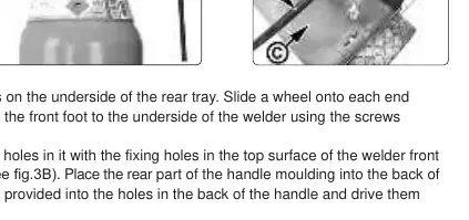
- Wheels and Foot: Slide the rear axle through the tray loops, attach wheels with washers and split pins, and screw the front foot to the underside.
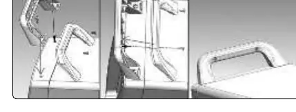
- Handle: Align the front handle moulding with the top surface, secure with two bolts, attach the rear moulding, and fasten with two self-tapping screws.
- Gas Cylinder: Place the cylinder on the rear tray, secure it with the provided chain, and connect the regulator using the bull nose adaptor (if required). Connect the gas tube to the inlet nozzle and secure with wire clips.
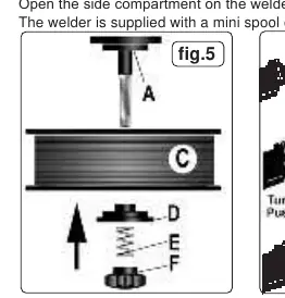
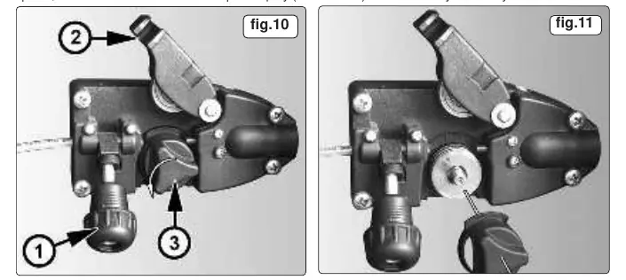
- Wire Reel: Open the side compartment. Remove the pressure knob, spring, and top disc. Place the wire reel on the spindle, ensuring it feeds forward. Replace the disc, spring, and knob, tightening until a mild braking effect is achieved.
Operation
To begin welding, you must feed the wire through the torch:
- Remove the gas cup and contact tip from the torch.
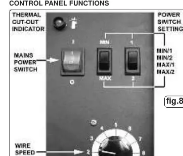
- Set the voltage switches to MIN/1 and the wire speed knob to 5 or 6.
- Connect to mains power and press the torch switch until the wire feeds through.
- Switch off, replace the contact tip and gas cup, and trim the wire.
- Wire Tension: Adjust the tension screw so the pressure roller provides enough grip without deforming the wire.
- Welding: Ensure the negative lead is securely attached to the workpiece. Clean the weld area of paint, rust, and grease.
Maintenance
Regular maintenance ensures consistent performance:
- Wire Feed Unit: Clean rollers weekly, especially the feed roller groove.
- Torch: Clean the liner with compressed air. Replace if blocked.
- Consumables: Keep the gas cup and contact tip free from spatter. Use anti-spatter spray. Replace the contact tip if the bore becomes enlarged or oval.
- Feed Roller: The roller has two grooves (0.6mm and 0.8mm). Flip the roller to match the wire size being used.
Troubleshooting
If you encounter issues, check the following:
- No weld current: Check the earth lead connection, torch lead, or the fuse in the plug.
- Wire does not feed: Check wire tension, clean the torch liner, or check for a defective gas cup/tip.
- Unstable arc: Verify settings, clean the weld area, or replace a worn gas cup.
- Porous weld: Ensure gas is flowing, the gas cup is clean, and the torch is held at the correct distance (8-10mm).
Manufacturer information
Sealey Group
Practical help
Common problems
No weld current
Check earth lead connection, ensure clamp is on clean metal, or check for a blown fuse in the 13A plug.
Wire does not feed
Adjust wire tension, clean the torch liner with compressed air, or check for deformed wire.
Unstable arc
Check control panel settings, clean impurities from the weld area, or replace a worn gas cup.
Porous weld
Check gas supply, ensure gas cup is not clogged, and maintain a torch distance of 8-10mm.
Before use
- Inspect power supply leads and plugs for wear.
- Ensure gas cylinder is secured vertically.
- Check that the wire feed roller groove matches the wire size (0.6mm or 0.8mm).
- Ensure the earth clamp is securely attached to the workpiece.
- Verify the torch liner is clean and undamaged.
Specs in practice
- Welding Current
- 30-150A range, adjustable via control panel switches.
Images and diagrams
- Fig 1-2: Gas cylinder and regulator setup.
- Fig 3: Handle assembly instructions.
- Fig 5-7: Wire reel installation and feed roller adjustment.
- Fig 8: Control panel functions.
- Fig 9: Torch and gas cup components.
Model compatibility
- Accepts wire spools up to 5kg.
- Requires 16A industrial plug for full capacity usage.
- Not suitable for use with non-regulated generators.

Manual page author
Emily Carter
User documentation editor
Prepares concise manual descriptions and highlights the most useful setup, operation, and maintenance information for readers.