HVAC / Ventilation Systems
User Manual for Manrose 125mm Low Profile Inline Extraction Fan Kit
Comprehensive user manual for the Manrose 125mm Low Profile Inline Extraction Fan Kit (models FAN0616 and FAN0617). Includes detailed installation instructions, electrical wiring diagrams for standard and timer models, timer adjustment...
Table of contents
Manual images
Click an image to enlargeQuick Guide
This manual covers the installation and operation of the Manrose 125mm Low Profile Inline Extraction Fan Kit. The system is designed for ventilation within shower cubicles and other areas. Installation must be performed by a registered electrician in accordance with AS/NZS3000 wiring rules.
- Models: FAN0616 (Standard Switching), FAN0617 (Timer Switching).
- Key Requirement: The fan must be installed with fixed wiring; flexible cords are not permitted.
- Safety: Ensure the main electricity supply is turned off before installation.
- Timer Adjustment: The timer on model FAN0617 is adjustable via a rotary switch on the PCB.
Safety Precautions
To reduce the risk of fire, electric shock, and personal injury, observe the following:
- Do not use the fan near baths, swimming pools, or wet areas.
- Ensure the supply voltage matches the product rating.
- The fan must be installed at least 2.1m above the floor.
- Keep air inlets and outlets clean and free of blockages.
- Do not cover the fan.
- Do not use in areas where flammable liquids or gases are stored.
Installation
Follow these steps for a successful installation:
- Grille Selection: Choose between circular eggcrate or square low-profile fascia.
- Ceiling Preparation: Cut a 125mm hole (or 130mm if using gib-fixing clips). Ensure the area above is free from obstructions.
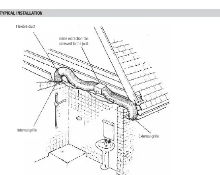
- Mounting: Secure the fan unit to a joist using the fixing bracket and two screws. Ensure the discharge end (with the back draught shutter) is oriented correctly according to the airflow arrow.
- Ducting: Attach flexible ducting to the fan and grilles using the provided duct tape. Keep the ducting as straight as possible to maximize performance.
- Exterior Grille: Install the weatherproof cowl or fixed grille on the soffit or outside wall.
Electrical Connections
All electrical work must be carried out by a registered electrician.
- Standard Model (FAN0616): Connect to a light switch or a dedicated fan switch.
- Timer Model (FAN0617): Connect to a light switch or dedicated fan switch. The fan will run for a pre-set time (1 to 20 minutes) after the switch is turned off.
- Wiring: Use a minimum cable section of 1mm².
Timer Adjustment
For the timer model (FAN0617), the time delay can be adjusted:
- Switch off the power to the fan.
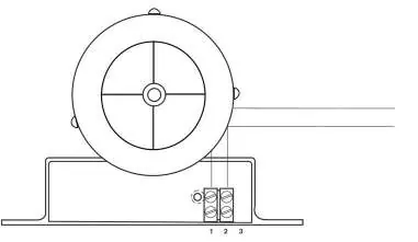
- Remove the cover to access the PCB.
- Locate the rotary adjuster wheel.
- Rotate to the right (+) to increase the time or to the left (-) to decrease the time.
- Replace the cover before restoring power.
Specifications
- Duct Size: 125mm
- Supply: 220-240V AC, 50Hz
- Sound Level: 45 dB(A)
- Max Operating Temp: 50°C
- Fan Type: Centrifugal
Practical help
Common problems
Fan does not start
Check that the main electricity supply is on and that the light switch or dedicated fan switch is correctly wired.
Timer duration is too short or too long
Adjust the rotary switch on the PCB (ensure power is off before opening the cover).
Poor airflow performance
Check the ducting for excessive bends, restrictions, or blockages. Ensure the ducting is as straight as possible.
Before use
- Verify that the supply voltage matches the product rating label.
- Ensure the installation is performed by a registered electrician.
- Check that the area above the ceiling is free from obstructions.
- Ensure the fan is mounted at least 2.1m above the floor.
- Confirm that the ducting is securely attached with the provided tape.
Specs in practice
- Max Operating Temp
- 50°C, the maximum ambient temperature the fan can withstand.
Images and diagrams
- Fig 1: Wiring diagram for the Standard Switching model (FAN0616).
- Fig 2: Wiring diagram for the Timer Switching model (FAN0617), including the PCB board and rotary switch adjustment.
Model compatibility
- Not suitable for use in the immediate vicinity of baths or swimming pools.
- Requires fixed wiring; do not use flexible cords.
- Must be installed in accordance with AS/NZS3000 wiring rules.

Manual page author
Michael Turner
Technical manual editor
Reviews PDF manuals for structure, safety notes, and practical product details so readers can find the right information quickly.