HVAC / Ventilation Systems
Manrose 150mm Low Profile Inline Extraction Fan Kit
Comprehensive installation and wiring guide for the Manrose 150mm Low Profile Inline Extraction Fan Kit. Includes step-by-step mounting instructions, electrical wiring diagrams for standard and timer models, and safety guidelines.
Table of contents
Manual images
Click an image to enlargeQuick guide from the manual
This manual provides installation and wiring instructions for the Manrose 150mm Low Profile Inline Extraction Fan Kit. Important: All electrical work must be carried out by a registered electrician in accordance with AS/NZS3000 wiring rules. Ensure the main electricity supply is turned off before beginning any installation work.
Product Description
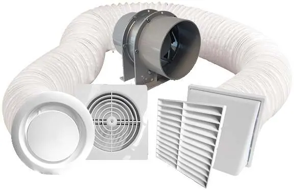
The Manrose inline extraction fan kit is designed for ventilation within a shower cubicle. The kit includes the fan unit, interior grille, exterior grille, and flexible ducting. The fan features an EC Axial motor and is designed for high-performance extraction.
Installation
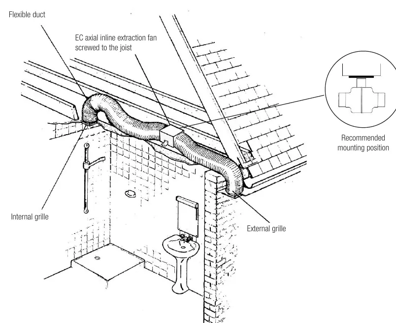
Installation involves mounting the interior grille, the fan unit, and the exterior grille, connected by flexible ducting.
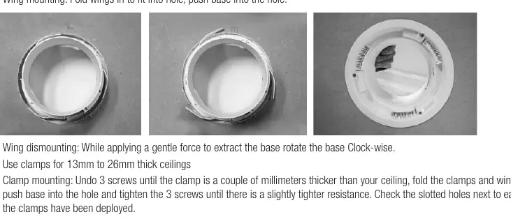
- Interior Grille: Cut a hole in the ceiling (155mm, 165mm, or 195mm depending on the grille type). Use the provided wings or clamps to secure the grille to the ceiling.
- Fan Mounting: Secure the fan unit to a joist using two screws through the fixing bracket. Ensure the discharge end (where the fan blade is visible) is oriented correctly, following the airflow arrow on the unit.
- Ducting: Attach the flexible duct to the fan spigot and the grilles using the provided duct tape. Keep the ducting as straight as possible to maintain performance. Do not cut the duct too short until the grille is screwed to the outside surface.
- Exterior Grille: Select a position on the soffit or outside wall. Remove the grille insert, cut a 160mm hole, and secure the grille.
Electrical Connections
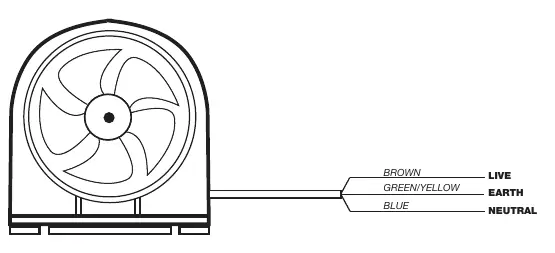
The fan must be installed using fixed wiring; do not use a flexible cord. Wiring must be performed by a registered electrician.
- Standard Switching (Model FAN0618): Connect the fan to the light switch or a dedicated fan switch so it activates when the switch is turned on.
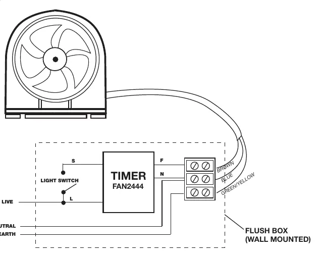
- Timer Switching (Model FAN0619): Connect the fan to the light switch or a dedicated fan switch. The timer is adjustable for 0-20 minutes of run-on time and includes a 0-5 minute delay setting for switching the fan on. Use only the specified FAN2444 timer model.
Safety and Maintenance
- Ensure the fan is installed at least 2.1m above the floor.
- Keep air inlets and outlets clean and free of dust or blockages to prevent overheating.
- Do not use the fan near baths, swimming pools, or wet areas.
- Do not allow bare skin to touch hot surfaces while the fan is in use.
- If the supply cord is damaged, it must be repaired or replaced by the manufacturer or an appointed representative.
Practical help
Common problems
Fan does not start
Ensure the main power is on and the light switch or dedicated fan switch is activated. Verify all wiring connections match the provided diagrams.
Timer not functioning as expected
Ensure the correct timer model (FAN2444) is installed. Do not use old models (with resistor) or FAN0372. Check wiring against Diagram 2.
Excessive noise or vibration
Ensure the fan is securely screwed to the joist. Check that ducting is not kinked or restricted.
Before use
- Turn off the main electricity supply before starting installation.
- Verify the supply voltage matches the product rating label.
- Ensure the installation location is at least 2.1m above the floor.
- Check that the area above the ceiling is free from obstructions.
- Confirm a registered electrician is available for all electrical work.
Images and diagrams
- Diagram 1: Wiring for Standard Switching model FAN0618.
- Diagram 2: Wiring for Timer Switching model FAN0619.
Model compatibility
- Requires fixed wiring; do not use a flexible cord.
- Compatible with FAN2444 timer; do not use old FAN2444 (with resistor) or FAN0372.

Manual page author
Emily Carter
User documentation editor
Prepares concise manual descriptions and highlights the most useful setup, operation, and maintenance information for readers.