HVAC / Ventilation Systems
Service and Accessories Installation Manual for Systemair SAVE VTR 150/B
Comprehensive service and accessories installation guide for the Systemair SAVE VTR 150/B ventilation unit. Includes configuration, troubleshooting, electrical connections, and accessory setup.
Table of contents
Manual images
Click an image to enlargeQuick guide from the manual
The Systemair SAVE VTR 150/B is a ventilation unit configured via the SAVE Touch control panel or a mobile application. Upon first power-up, the mandatory Startup Wizard guides you through setting the menu language, time and date, configuration file import, airflow control type, heater type, and filter change timer. Note that the Startup Wizard is skipped if the SAVE LIGHT control panel is used.
Configuration
The unit features various user modes to manage airflow and temperature:
- Permanent modes: Auto (automatic control based on demand/schedule) and Manual (four speed levels: Off/Low/Normal/High).
- Temporary modes: Holiday, Crowded, Away, Refresh, and Fireplace. These are active for a set period before reverting to the previous mode.
- Digital input functions: Central Vacuum Cleaner and Cooker Hood, which trigger specific airflow settings when activated via external signals.
Temperature settings can be adjusted between 12°C and 30°C. The unit also supports Demand Control for indoor air quality (IAQ) using CO2 and humidity sensors, which automatically adjust airflow based on air quality levels.
Service and Maintenance
The unit requires regular maintenance, including filter replacement and cleaning of fans and heat exchangers. The Service menu, protected by a default password (1111), allows for advanced configuration of inputs, outputs, and control regulation. The main circuit board and connection box are located within the unit, providing terminals for various accessories and sensors.
Troubleshooting
If issues arise, check the following:
- Fans do not start: Check for alarms on the control panel, verify fuses, and ensure fast couplings are connected.
- Reduced airflow: Check for active alarms, ensure the unit is not in defrost mode, verify filter status, and check for clogged ducts or louvres.
- Unit not controllable: Reset by disconnecting mains power for at least 10 seconds and check modular contact connections.
- Low supply air temperature: Check for alarms, verify set temperature, ensure ECO mode is not preventing heater activation, and check if the overheat protection thermostat needs resetting.
Accessories Installation
The unit supports numerous accessories, including:
- Internet Access Module (IAM): Enables remote control via mobile app or computer.
- IAQ Sensors: CO2, humidity, and temperature sensors for demand-controlled ventilation.
- Heaters and Coolers: Electric duct heaters, water heaters, and water coolers.
- Dampers and Pressure Guard: For airflow control and pressure monitoring.
- Control Panels: Multiple panels can be connected using diverting plugs.
- Presence Detectors and Push Buttons: For triggering specific functions.
Detailed wiring and configuration steps for each accessory are provided in the manual, typically requiring connection to the main circuit board or connection board and subsequent configuration in the Service menu.
Practical help
Common problems
Fans do not start
Check the control panel for alarms, verify all fuses and fast couplings are connected, and ensure the week schedule is not set to OFF.
Reduced airflow
Check for alarms, verify if the unit is in defrost mode, check filters for pollution, and inspect ducts/louvres for blockages.
Low supply air temperature
Check for alarms, verify set temperature, ensure ECO mode is not active, and check if the overheat protection thermostat needs to be reset.
Unit cannot be controlled
Reset control functions by disconnecting mains power for at least 10 seconds and check the modular contact connection between the control panel and the main circuit board.
Before use
- Ensure all warning signs are legible.
- Verify that filters are mounted before starting the unit.
- Check that all electrical connections are carried out by an authorized installer.
- Ensure duct connections are covered during storage and installation.
- Check that the mains supply is disconnected before performing any maintenance.
Specs in practice
- Re-heater power
- Available in 500 W or 1000 W versions.
- Temperature range
- 12–30°C for standard temperature settings.
Images and diagrams
- Fig. 1: Type label location and description of codes.
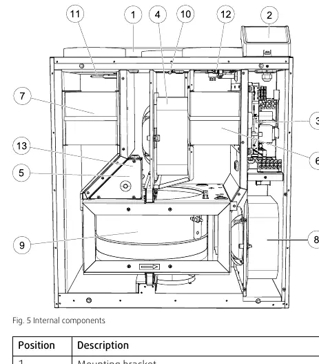
- Fig. 5: Internal components layout.
- Fig. 7: Main circuit board connections.
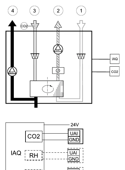
- Fig. 9: IAQ sensor connection diagram.
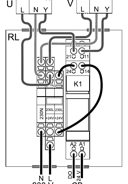
- Fig. 13: Damper connection diagram.
Model compatibility
- Advanced settings cannot be performed using the SAVE LIGHT control panel.
- Room temperature control mode requires an accessory to measure room temperature.
- Moisture transfer function is only available for units with a Rotating type heat exchanger.
- Defrosting control is available if the heat exchanger type is set as Plate.

Manual page author
Emily Carter
User documentation editor
Prepares concise manual descriptions and highlights the most useful setup, operation, and maintenance information for readers.