Power / EV Chargers
Maverick 033D-80A EV Charger User Manual
Quick guide for the Maverick 033D-80A EV Charger. Includes installation, wiring, charging operations, and troubleshooting fault codes.
Table of contents
Manual images
Click an image to enlargeQuick guide from the manual
This document provides essential information for the installation, operation, and maintenance of the Maverick 033D-80A EV Charger. Always ensure the device is installed by a professional and that the circuit breaker is sized at 125% of the load in accordance with local electrical codes. Do not use the device if the housing or cables are damaged.
Product Overview
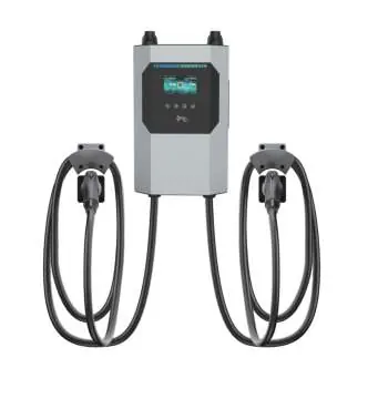
The Maverick 033D-80A is an AC EV charger designed for electric vehicles that do not require ventilation during charging. It features a 4.3-inch LCD screen, RFID authentication, and supports network configuration via WiFi or Ethernet.
Installation
Location Requirements: Install the unit in a ventilated, cool place away from direct sunlight and rain. Ensure the unit is mounted vertically with sufficient clearance (at least 200mm on sides, 300mm above, 500mm below).
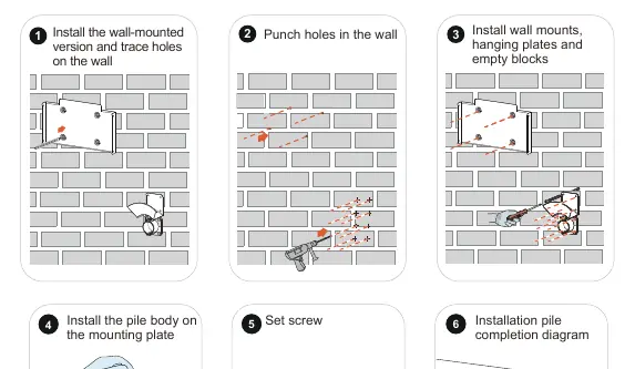
Wall Mount Steps:
- Trace and punch holes in the wall according to the mounting plate.
- Install wall mounts, hanging plates, and empty blocks.
- Secure the pile body onto the mounting plate using the provided screws.
Wiring
Bottom Wiring Procedure:
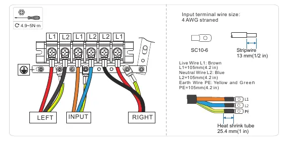
- Remove the decorative cover and the wiring cover.
- Connect the input wires (L1, L2, PE) to the terminals.
- Ensure the copper cable cross-section is 3*4 AWG.
- Tighten connections to the specified torque (1.2~2N·m for covers, 4.9~5N·m for terminals).
- Reinstall the wiring and decorative covers.
Operations
Charging Process:
- Park the vehicle and ensure it is in a chargeable state.
- Connect the charging cable to the car socket.
- Start charging via RFID card, APP, or plug-and-charge mode.
- Monitor the screen for charging voltage, current, and time.
- To end, stop via the APP or by selecting the coupler on the screen, then unplug the cable.
Status Indicators
The charger uses an LED light bar to indicate status:
- Green (Flash): Standby/Ready.
- Blue (Always on): Charging.
- Purple (Always on): Charging Complete.
- Red (Always on/Flash): Fault detected.
- Yellow (Always on): Out of Service.
Troubleshooting
If a fault occurs, the charger will display a code. Common issues include:
- 20 Flash Fault: Memory chip damaged; contact support.
- 24 Ground Fault: Check grounding of the charging pile.
- 25 Over Temperature: Equipment too hot; wait for temperature to drop.
- 33/43 Input Overvoltage: Check input cable and grid voltage.
Maintenance
Perform regular monthly maintenance. Ensure the equipment is well-grounded, check for safety hazards (high temperature, corrosion, flammable items), and verify that all wiring terminals are tight and in good contact.
Practical help
Common problems
20 Flash Fault
Memory chip is damaged; contact after-sales service.
24 Ground Fault
The charging pile is not grounded; test the circuit.
25 Motherboard Over Temperature
Equipment temperature is too high; wait for it to drop.
33/43 Cable Input Overvoltage
Check if the input cable is connected correctly and verify grid voltage.
Before use
- Verify that the mainboard power switch is off before installation.
- Ensure the charging pile is installed in a ventilated, cool place.
- Check that the model and specifications match your order.
- Ensure the circuit breaker is sized at 125% of the load.
- Verify the input voltage is 208/240VAC.
Specs in practice
- Operating Temperature
- -30°C to 50°C.
- Enclosure Protection
- Type 4, IK08 rating.
- Cable Length
- Standard 18ft.
Images and diagrams
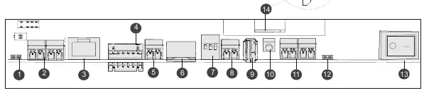
- Block diagram illustrates power flow, relay controls, and communication modules.
- Wiring diagrams show connections for single and dual charge couplers.
Model compatibility
- Compatible with electric vehicles not requiring ventilation during charging.
- Requires hardwired connection via pigtail (L1/L2/GND).

Manual page author
David Miller
Documentation analyst
Organizes user manual content into clear summaries, with attention to model details, product context, and everyday usability.