Power / EV Chargers
User Manual for depow 11kW Wallbox with Cable
Quick guide for the depow 11kW Wallbox. Includes installation steps, wiring instructions, Wi-Fi setup via Tuya Smart app, LED status indicators, and troubleshooting error codes.
Table of contents
Manual images
Click an image to enlargeQuick Start Guide
The depow 11kW Wallbox is designed for electric vehicle charging. To begin, connect the inlet cable to the meter box, adjust the current and delay settings, and connect the Type 2 charging cable to your vehicle. Note that settings cannot be modified once the connector is plugged into the vehicle.
Operating Instructions
The wallbox features a single button for various functions:
- Press 1x: Adjust current (6A/8A/10A/13A/16A).
- Press 2x: Enter Wi-Fi configuration mode (only in standby).
- Press & Hold (Standby): Set delay time (0.5h-8h).
- Press & Hold (Charging): Pause charging.
- RFID Card Sensing: Plug and play is default. Swipe card for 10s to enable RFID function.
If the charger remains inactive for over 5 minutes, it enters sleep mode. Reactivate by clicking the button, swiping the RFID card, or plugging in the Type 2 connector.
Installation
Wall Mounting:
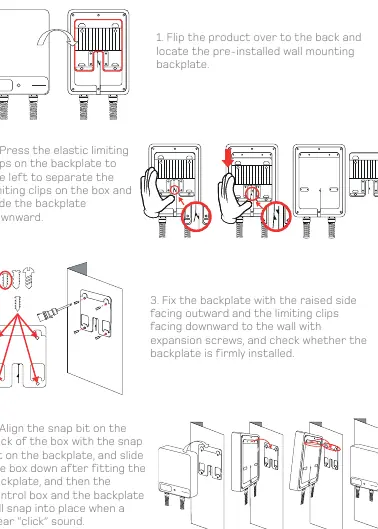


- Flip the product to locate the pre-installed backplate.
- Press the elastic limiting clips to the left to separate the backplate and slide it downward.
- Fix the backplate to the wall using expansion screws, ensuring the raised side faces outward and clips face downward.
- Align the snap bit on the back of the box with the backplate and slide the box down until it clicks into place.
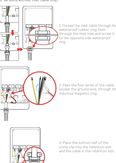
Wiring Connection:
- Thread the inlet cable through the waterproof rubber ring and inlet hole.
- Pass the four wires (L1, L2, L3, N) through the inductive magnetic ring, excluding the ground wire.
- Connect wires to the corresponding copper pillars on the PCB: Brown to L1-in, Black to L2-in, Gray to L3-in, Blue to N-in, and Green/Yellow to PE.
- Secure the crimp clips and tighten the waterproof rubber rings to complete the installation.
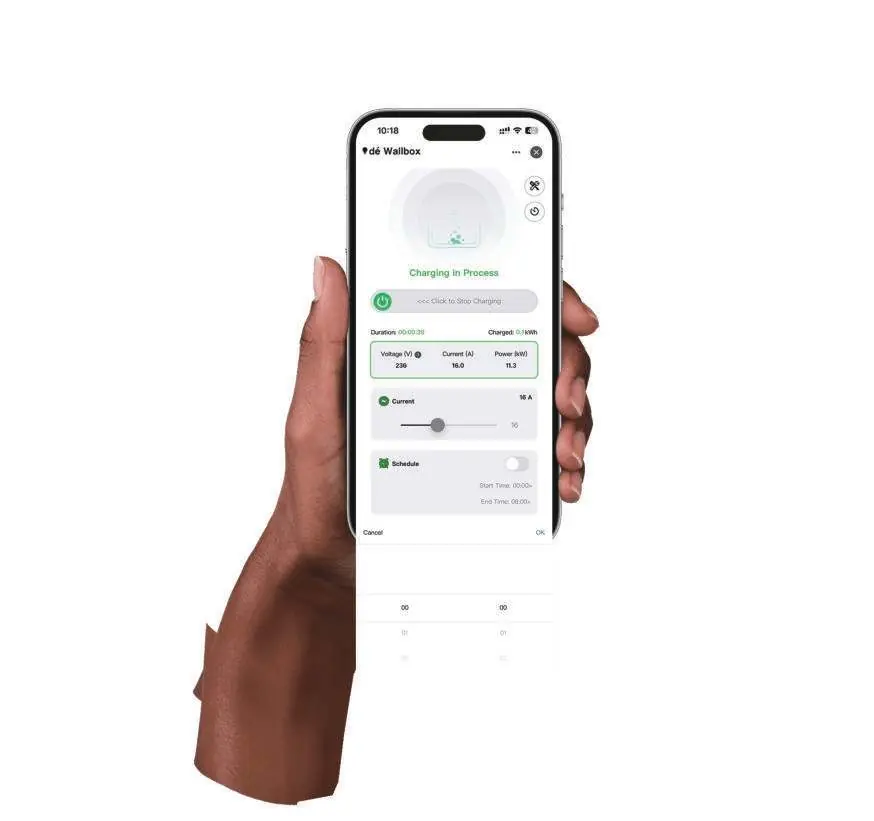
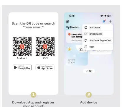
Wi-Fi Setup
Download the Tuya Smart app. Ensure your mobile device is connected to a 2.4GHz Wi-Fi network with Bluetooth enabled. Follow the in-app instructions to add the device, enter Wi-Fi credentials, and complete the connection.
LED Status & Error Codes
The LED screen provides real-time data on current, voltage, power, and charging status. If an error occurs, the LED will indicate a code:
- 0 (System Error): Power off and contact support.
- 1 (Leakage Current): Power off and check vehicle/charger.
- 2 (Overcurrent): Power off and check vehicle.
- 3 (Over/Undervoltage): Power off and check distribution grid.
- 4 (Ground Protection): Power off and check distribution grid.
- 5 (Relay Sticking): Power off, connect power plug first, then Type 2.
- 6 (CP Fault): Power off and reconnect.
- 7 (Overtemperature): System will auto-reduce or manually set a lower current.
Safety Information
Use only for electric vehicles. Do not open the enclosure or attempt repairs. Ensure the unit is connected to a properly grounded outlet or grid. The wallbox is IP54 rated, and the Type 2 connector is IP55 when coupled; avoid use during heavy rain.
Practical help
Common problems
System Error (Code 0)
Power off the unit and contact customer support.
Leakage Current Detected (Code 1)
Power off and check both the vehicle and the charger.
Overcurrent Protection (Code 2)
Power off and check the vehicle.
CP Fault (Code 6)
Power off and reconnect the charging cable.
Before use
- Ensure the wallbox is within Wi-Fi signal coverage.
- Verify the mobile device is connected to a secure 2.4GHz Wi-Fi network.
- Ensure Bluetooth is enabled on the mobile device.
- Check that the wallbox is not already linked to another account.
- Ensure the wallbox is installed on a properly grounded grid.
Specs in practice
- Operating Temperature
- -25°C to +55°C
Images and diagrams
- Wiring diagram illustrates the connection of L1, L2, L3, N, and PE wires to the PCB terminals.
- Installation diagram shows the backplate removal and wall mounting process.
Model compatibility
- Compatible with electric vehicles using Type 2 charging cables.
- Requires 2.4GHz Wi-Fi network for app-based features.
- Not compatible with 5GHz Wi-Fi networks.

Manual page author
Emily Carter
User documentation editor
Prepares concise manual descriptions and highlights the most useful setup, operation, and maintenance information for readers.