Tools / Power Tools
Permeability Plugging Tester OFITE 171-84-10K
Quick guide for the OFITE 171-84-10K Permeability Plugging Tester. Includes setup, testing procedures, safety warnings, maintenance, and component assembly instructions.
Table of contents
Manual images
Click an image to enlargeQuick guide from the manual
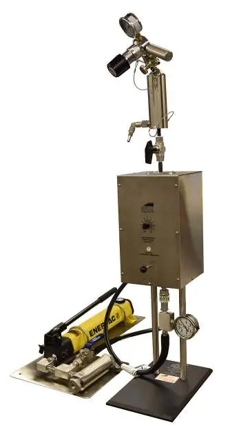
The Permeability Plugging Tester (PPT) is a specialized instrument used for performing filtration tests on plugging materials. It is designed to predict how drilling fluids form low-permeability filter cakes to seal off depleted intervals. The system operates by pressurizing a test cell with hydraulic oil via a hand pump, with a floating piston separating the oil from the test fluid.
Safety precautions
- Temperature: The heating jacket, test cell, and valve stems become extremely hot. Always wear protective clothing.
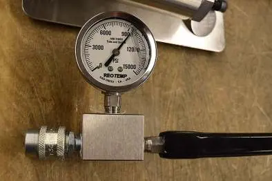
- Pressure: The maximum working pressure is 10,000 psi (69 MPa). Never exceed this limit.
- Gas Usage: Only use Carbon Dioxide or Nitrogen for pressurization. Never use Nitrous Oxide, Oxygen, or compressed air, as these are dangerous at high temperatures.
- Safety Shield: Use a safety shield (#171-06) during testing to protect personnel.
- O-rings: Inspect all O-rings before every test. Use Viton 75D (black) for tests up to 400°F and Viton 90D (green) for tests up to 500°F.
Specifications
- Maximum Pressure: 10,000 psi (69 MPa)
- Maximum Temperature: 500°F (260°C)
- Heater: 800W
- Weight: 61 lb (27.7 kg)
- Dimensions: 15" × 25" × 42"
Preparation
- Plug the heating jacket into a power source and preheat to 10°F (6°C) above the target test temperature.
- Soak the ceramic disk in the appropriate base fluid (water, brine, diesel, or synthetic) for at least 10 minutes.
Cell assembly
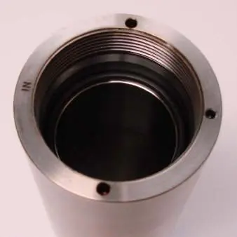
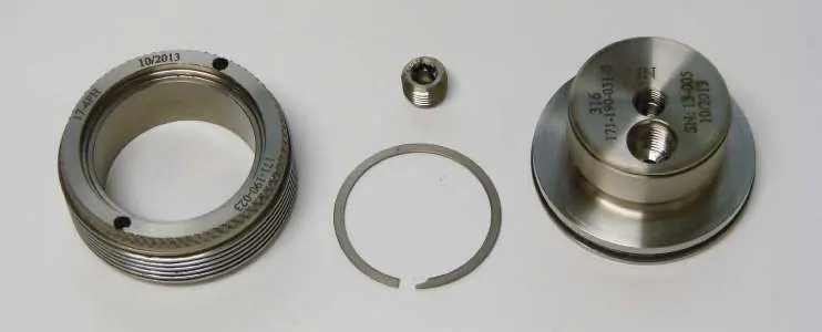
- Inspect all O-rings and apply a thin film of silicone grease.
- Place an O-ring on the shoulder inside the cell body and in the groove around the cell cap.
- Apply anti-seize compound to the threads of the cell caps and valve stems.
- Screw the inlet cell cap into the cell body.
- Place the cell into the heating jacket with the inlet side pointing down.
- Assemble the piston with two O-rings (#171-99) and insert it into the cell.
- Connect the inlet pressure manifold to the inlet pressure assembly, ensuring quick-connect fittings are fully engaged.
- Pour test fluid into the cell, keeping the level just below the O-ring shoulder.
- Place the ceramic disk on top of the O-ring and screw on the outlet cell cap.
- Fill the outlet valve stem assembly with base fluid using a syringe before attaching the back pressure receiver.
Testing procedure
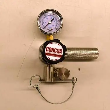
- Set the back pressure using the CO2 pressure assembly according to the recommended minimum back pressure chart.
- Stroke the pump to apply pressure to the cell.
- Once the target temperature is reached, apply the working test pressure.
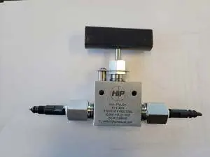
- Open the outlet ball valve to initiate filtration.
- Collect filtrate at 15 seconds, 7.5 minutes, and 30 minutes.
- After the test, turn off the heater and allow the cell to cool to room temperature before releasing pressure.
Data analysis
The filtration area is 3.55 in² (22.9 cm²). To compare results with standard filtration tests (7.1 in²), double the total filtrate volume collected. Spurt loss can be calculated using the formula: V1 = 4V7.5 - 2V30.
Maintenance
- Thoroughly clean and dry all components with water and soap or an appropriate solvent after each test.
- Periodically check the cell assembly for leaks by pressurizing and immersing in water.
- Inspect the power cord for insulation wear.
- If the regulator leaks or creeps, repair the regulator seat.
Manufacturer information
OFI Testing Equipment, Inc.
Practical help
Common problems
Gas leak at regulator outlet
Repair the regulator (seat leak or creep).
Outlet pressure increases while downstream valves are closed
Repair the regulator (seat leak or creep).
Gas leak from relief valve
Replace the valve or repair the regulator.
Inconsistent repeat readings
Repair the regulator or replace the pressure gauge.
Before use
- Inspect all O-rings for damage or wear.
- Ensure all threads are clean and free of debris.
- Apply grease to all O-rings.
- Soak ceramic disk in base fluid for at least 10 minutes.
- Preheat heating jacket to 10°F above test temperature.
- Verify the pressure release valve on the pump is closed.
Specs in practice
- Max Pressure
- 10,000 psi (69 MPa)
- Max Temperature
- 500°F (260°C)
- Heater Power
- 800W
Images and diagrams
- The PPT is an inverted HTHP filter press configuration.
- The cell is pressurized with hydraulic oil via a hand pump.
- A floating piston separates the hydraulic oil from the test fluid.
Model compatibility
- Use only Carbon Dioxide or Nitrogen for pressurization.
- Do not use Nitrous Oxide, Oxygen, or compressed air.
- Use Viton 75D O-rings for tests up to 400°F.
- Use Viton 90D O-rings for tests up to 500°F.

Manual page author
David Miller
Documentation analyst
Organizes user manual content into clear summaries, with attention to model details, product context, and everyday usability.