Electronics / Security Systems
Operating Instructions for i-PRO CCU GP-CS44X10-0
Quick guide for the i-PRO CCU GP-CS44X10-0 camera control unit. Includes installation steps, connection diagrams, button functions, and troubleshooting tips.
Table of contents
Manual images
Click an image to enlargeQuick Guide
This document provides basic operating instructions for the i-PRO CCU (Camera Control Unit) model GP-CS44X10-0. Before connecting or operating the product, ensure the unit is placed horizontally on a stable surface. Always turn off the power (stand-by) before connecting or disconnecting the camera cable. The unit is designed for professional indoor use only.
Parts and Functions
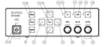
Front Panel: Features the power switch, menu navigation buttons (Menu, Page, Profile, Up, Down, Left, Right, Select), and dedicated controls for Image Enhancement (IE), White Balance (WB), Auto Exposure (AE), and manual gain/level adjustments.
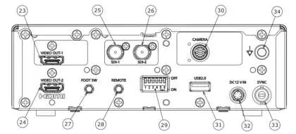
Rear Panel: Contains the primary connectivity ports, including HDMI output connectors (HDMI OUT 1/2), SDI output connectors (SDI-1/2), a camera cable connector, a foot switch terminal, a remote terminal, a USB 2.0 port for profile management, a 12V DC power input, and a sync terminal.
Installation
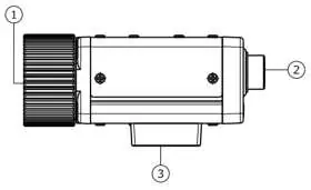
Camera Mounting: The camera head can be secured to a tripod using the 1/4-20 UNC tripod socket hole. Ensure both the tripod and CCU are placed horizontally.
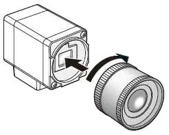
Lens Mounting: The unit uses a C-mount lens. To mount: 1. Remove the cap from the lens mount section. 2. Turn the C-mount lens clockwise to engage it. Ensure the optical filter is clean before mounting. Use lenses with an aperture of F4.0 to F16 to avoid image blurring.
System Configuration
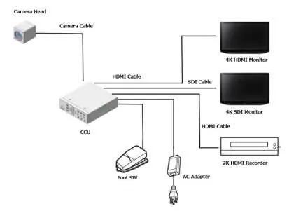
The system typically consists of the Camera Head connected to the CCU via a specific camera cable (GP-UC532G**A). The CCU connects to monitors via HDMI or SDI cables. External devices such as a foot switch or AC adapter can also be connected.
Troubleshooting
If you encounter issues, check the following:
- No image displayed: Verify cable connections, ensure the video output format is compatible with the monitor, and check monitor settings.
- FAN STOPPED message: Turn off the power immediately and contact your dealer for fan replacement.
- Blurred screen: Adjust the lens aperture; use recommended F-numbers.
- Unsupported Camera Head: Ensure the connected camera head is compatible with the CCU.
Specifications
Power: 12V DC, 2.7A (including camera head).Operating Temperature: 0°C to 40°C (32°F to 104°F).Operating Humidity: 30% to 90% (without condensation).Dimensions: 185 mm (W) x 57 mm (H) x 206 mm (D).Weight: Approx. 1.5 kg.
Practical help
Common problems
No image displayed
Check if cables are connected properly, verify video output format compatibility with the monitor, and ensure monitor contrast/luminance settings are correct.
FAN STOPPED message displayed
Turn off the power immediately and contact your dealer for fan replacement.
Blurred whole screen
Adjust the lens aperture. Use lenses with an F-number of F4.0 or higher.
Unsupported Camera Head message
The connected camera head is not compatible with this CCU. Contact your dealer.
Before use
- Ensure the CCU and tripod are placed horizontally.
- Verify the power supply is 12V DC.
- Check that the lens mount projection is 4mm or less.
- Ensure the operating environment is between 0°C and 40°C.
- Turn off the CCU before connecting or disconnecting the camera cable.
Specs in practice
- Operating Temperature
- 0°C to 40°C (32°F to 104°F).
Images and diagrams
- Front Panel: Contains power switch, menu navigation, and status indicators.
- Rear Panel: Contains HDMI/SDI outputs, camera cable connector, and power input.
Model compatibility
- Compatible with specific 1-4MOS camera heads (e.g., GP-H143CX0-0F, GP-H343CX1-0F).
- Requires specific optional camera cables (GP-UC532G**A).

Manual page author
Emily Carter
User documentation editor
Prepares concise manual descriptions and highlights the most useful setup, operation, and maintenance information for readers.