Electronics / Security Systems
User Manual for Uniview Card Reader
Quick guide for the Uniview Card Reader. Includes installation steps, wiring diagrams, DIP switch configuration for Wiegand/RS485 modes, and status indicator explanations.
Table of contents
Manual images
Click an image to enlargeQuick guide from the manual
This document provides essential instructions for the installation, wiring, and configuration of the Uniview Card Reader. It covers both keypad and non-keypad models. Users should ensure the device is installed by a trained professional and adhere to all local electrical safety regulations.
Packing List
Ensure the package contains the following items:
- Card reader
- Screws and components (4 sets)
- Bracket
- Tail cable
- Tail cable cover plate
- Product documents
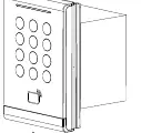
Product Overview
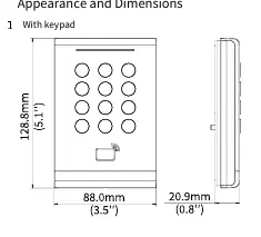
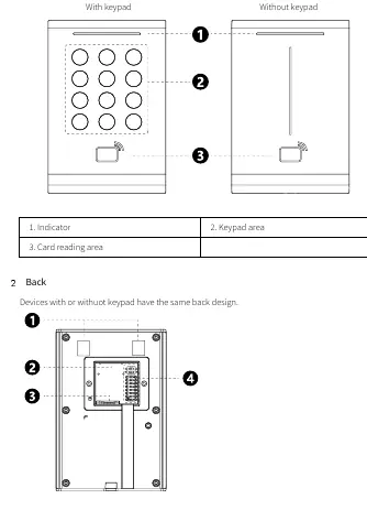
The device features a front panel with an indicator, keypad area (on specific models), and card reading area. The back of the device includes the bracket mounting groove, tail cable interface, PSAM card slot, and DIP switches for configuration.
Wiring and Connections
The tail cable provides the necessary interface for power and communication. Key connections include:
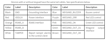
- Black: GND (Grounding)
- Red: VDD12V (Power)
- Orange/Yellow: RS485 interface
- White: TAMPER (Tamper alarm)
- Blue/Purple/Pink/Green/Brown: Wiegand output interface and LED/Buzzer control
Installation Steps
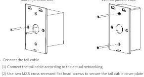
- Positioning: Determine the location for the 86mm or 115mm junction box.
- Bracket Mounting: Secure the bracket to the junction box using the provided M4*35 screws. Ensure the protruding side faces outward.
- Wiring: Connect the tail cable according to your network requirements. Secure the tail cable cover plate to the back of the reader using M2.5 screws.
- Final Assembly: Align the reader with the bracket, insert it, and secure it using the M3 truss head security screw from the bottom.
DIP Switch Settings
The DIP switches on the back of the device allow for mode selection and parameter adjustment:
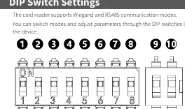
- Switch 1-4: RS485 address bits (Switch 5 must be ON).
- Switch 5: Card reader mode (ON: RS485, OFF: Wiegand).
- Switch 6: Wiegand protocol (ON: Wiegand 26, OFF: Wiegand 34).
- Switch 7: RS485 termination resistor (ON: Connect, OFF: Disconnect).
- Switch 8: Card security function (ON: Encrypted, OFF: Physical ID only).
Status Indicators
- Blinking blue, green, red: Startup successful.
- Steady blue: Normal operation.
- Steady green (1s): Card authentication successful.
- Steady red (1s): Card authentication failed.
- Constant beeps: Tamper alarm triggered.
Safety and Security
Always disconnect power before moving the device. Ensure proper ventilation and do not cover vents. For network security, change default passwords, keep firmware updated, and disable unused features like UPnP or SNMP.
Manufacturer information
Uniview
Practical help
Common problems
Constant beeps
Tamper alarm triggered. Check if the device is securely mounted and the tamper switch is engaged.
Three beeps
Card authentication failed. Ensure the card is valid and within the reading range.
Device not starting
Check power supply connection and ensure the voltage meets device requirements.
Before use
- Plan cable routing in advance.
- Prepare a Phillips screwdriver.
- Ensure an 86mm or 115mm junction box is installed.
- Verify power supply provides stable voltage.
- Check DIP switch settings for desired communication mode (RS485/Wiegand).
Images and diagrams
- DIP switch 5 determines the communication mode: ON for RS485, OFF for Wiegand.
- RS485 address is set using switches 1-4 when switch 5 is ON.
- Termination resistor (switch 7) should be ON for long-distance RS485 connections.
Model compatibility
- Supports 86*86mm and 115*73mm junction boxes.
- Encrypted authentication (Switch 8 ON) does not support door opening through NFC emulated cards.

Manual page author
David Miller
Documentation analyst
Organizes user manual content into clear summaries, with attention to model details, product context, and everyday usability.