Electronics / Security Systems
User manual for Uniview 0235C9KR Network Video Recorder
Quick guide for the Uniview 0235C9KR Network Video Recorder. Includes hardware installation, hard drive setup, interface overview, connection instructions, and initial network configuration.
Table of contents
Manual images
Click an image to enlargeQuick guide from the manual
This document provides essential setup and installation instructions for the Uniview Network Video Recorder (NVR). It covers hardware preparation, device connections, and initial software configuration. Please ensure you follow all safety guidelines provided in the manual.
Packing List
Before starting, ensure your package contains the following items:
- NVR Device
- HDD power cable
- HDD data cable
- Screw components
- Power adapter
- Mouse
- Product documents
Note: Package contents may vary depending on the specific device model and version.
Device Interfaces
The rear panel of the NVR includes the following ports:
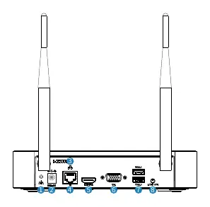
- Grounding terminal: For safety grounding.
- DC input: Power supply connection.
- Network interface: Ethernet connection.
- HDMI video output: For monitor connection.
- VGA video output: Alternative monitor connection.
- USB 2.0: For mouse or other peripherals.
- Audio output: For audio devices.
Indicator Lights
The front panel indicators provide status information:
- Operation: Steady on (normal), Blinking (starting up).
- Network: Steady on (connected), Off (not connected).
- Cloud status: Steady on (connected to cloud), Off (not connected).
- HDD: Steady on (no disk or starting), Blinking (normal operation), Fast blinking (disk faulty).
Device Installation
To install a hard disk drive (HDD):
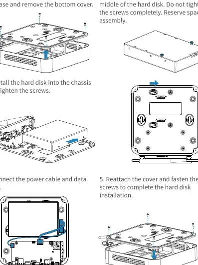
- Unscrew the four corner screws on the base and remove the bottom cover.
- Screw the two screws (3-5 turns) into the middle of the hard disk. Do not tighten completely.
- Install the hard disk into the chassis and tighten the screws.
- Connect the power cable and data cable to the HDD.
- Reattach the cover and fasten the four screws to complete the installation.
Device Connection
Follow these steps to connect your NVR:
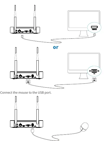
- Monitor: Connect the NVR to a monitor using either a VGA or HDMI cable.
- Mouse: Connect the mouse to the USB port.
- Power: Connect the camera and NVR to the mains power supply using the provided power adapters.
Web Login and App Setup
To access the device:
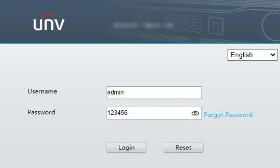
- Default IP address: 192.168.1.30
- Default username: admin
- Default password: 123456
Security Warning: It is strongly recommended to change the default password immediately upon first login. Use a strong password of at least nine characters, including uppercase and lowercase letters, digits, and special characters.
Local Settings
You can configure Wi-Fi and add cameras via the local interface:
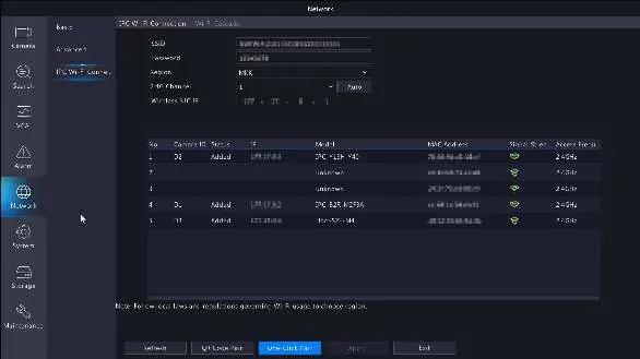
- Navigate to Menu > Network > IPC Wi-Fi Connection.
- To add cameras, reset the camera to factory settings and use the One-Click Pair or QR Code Pair options.
Manufacturer information
Uniview
Practical help
Common problems
HDD indicator is fast blinking
The disk is faulty. Check the connection or replace the disk.
Device not connected to network
Check the network cable connection and ensure the network indicator is on.
Cannot log in
Use the default credentials: username 'admin' and password '123456'. If changed, use the new password.
Before use
- Ensure the power supply meets the device requirements.
- Install the hard disk drive before powering on the device.
- Connect a monitor via HDMI or VGA.
- Connect the mouse to the USB port.
- Ensure the device is placed on a flat, stable surface with adequate ventilation.
Specs in practice
- 192.168.1.30
- Default IP address for web login.
- admin / 123456
- Default login credentials.
Images and diagrams
- The interface diagram identifies the grounding terminal, power input, network port, video outputs (HDMI/VGA), USB ports, and audio output.
- The installation diagram illustrates the step-by-step process of opening the chassis and securing the hard drive.
Model compatibility
- Use a UL certified power supply that meets LPS requirements.
- Only use the power adapter supplied with the device.

Manual page author
Michael Turner
Technical manual editor
Reviews PDF manuals for structure, safety notes, and practical product details so readers can find the right information quickly.