Automotive / Tyre Inflators
Pittsburgh 12V Twin Disc Car Horn
Quick guide for the Pittsburgh 12V Twin Disc Car Horn. Includes installation instructions, wiring diagram, safety precautions, and technical specifications for proper setup.
Table of contents
Manual images
Click an image to enlargeQuick guide from the manual
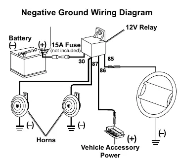
This document provides instructions for installing the Pittsburgh 12V Twin Disc Car Horn. The system requires a 12V DC power source and must be installed with a 15A fuse (not included) on the power supply wire to prevent electrical fire. The horns are designed for negative ground systems, which are standard in most vehicles.
Safety Information
- Electrical Safety: Always install a 15A fuse inline on the power supply wire. Failure to do so can cause an electrical fire.
- Installation Precautions: Wear ANSI-approved safety goggles and heavy-duty work gloves. Disconnect the vehicle battery before beginning installation.
- Environment: Do not install the horns in locations that exceed 212°F or where they may be submerged in water. Keep the horns sheltered from rain, road water, and mud splash.
- Operation: Exposure to noise levels over 85 dB is hazardous. Use hearing protection if working in close proximity to the horn.
Specifications
- Power Requirement: 12 Volts DC
- Volume: 108dB each
Installation Instructions
Before starting, ensure the vehicle is off, the transmission is in park (or reverse for manual), and the engine is cool. Disconnect the vehicle battery.
- Mounting: Select a location that shelters the horns from rain, road water, and mud. Avoid mounting near hot engine components or moving parts.
- Drilling: If drilling holes in the chassis, ensure no electrical wires, cables, or other vehicle components are in the drilling path.
- Securing: Mount the horns and the 12V relay to the chassis using nuts and bolts (not included). Point the horns forward and slightly down for maximum efficiency.
Wiring
Connect the horns and 12V relay according to the wiring diagram. Ensure all connections use terminal connectors (not included). Pay close attention to polarity. For positive ground systems, have a qualified mechanic perform the installation.
Parts List
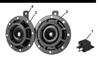
- 12V Relay
- High-Tone Supertone Horn
- Low-Tone Supertone Horn
- Mounting Bracket
Practical help
Common problems
Horn does not sound
Check the 15A inline fuse, verify all wiring connections, and ensure the relay is properly connected.
Risk of electrical fire
You must install a 15A fuse (not included) inline on the power supply wire.
Horn stops operating
Ensure the horns are not mounted in a location that exceeds 212°F or where they can be submerged in water.
Before use
- Disconnect the vehicle battery before starting installation.
- Obtain a 15A fuse (not included) for the power supply wire.
- Verify the vehicle uses a negative ground system.
- Wear ANSI-approved safety goggles and heavy-duty work gloves.
- Ensure the mounting location is protected from water and heat.
Specs in practice
- Power Requirement
- 12 Volts DC
Images and diagrams
- The wiring diagram illustrates the connection from the battery through a 15A fuse to the 12V relay, which then connects to the horns and vehicle accessory power.
Model compatibility
- Designed for negative ground systems (most vehicles).
- Not for use as a replacement for OEM horns.
- Requires professional installation for positive ground systems.

Manual page author
David Miller
Documentation analyst
Organizes user manual content into clear summaries, with attention to model details, product context, and everyday usability.