Automotive / Parts & Accessories
Metra 120E5000 SPDT Relay Installation Guide
Installation guide for the Metra 120E5000 SPDT relay. Includes wiring diagrams and instructions for common automotive applications like relay turn-on/off, trunk release, door locks, and antenna control.
Table of contents
Manual images
Click an image to enlargeQuick Guide from the Manual
The Metra 120E5000 is a Single-Pole, Double-Throw (SPDT) relay used for high-current switching in automotive applications. Before beginning any installation, verify all items received against your invoice. If you are running a wire directly to the battery for power, it is recommended to install a 30-amp fuse in-line, close to the battery connection. Always tape off any unused wires to prevent short circuits.
About the Relay
A relay acts as a switch controlled by a voltage input rather than manual action. By sending current through the relay, you can turn a device on or off without physically touching the device.
Wiring Connections
Proper wiring technique is essential for a reliable connection:
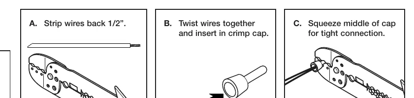
- Strip: Strip the wires back 1/2 inch.
- Twist: Twist the wires together.
- Crimp: Insert into a crimp cap and squeeze the middle of the cap for a tight connection.
Application: Relay Turn-On
Used for high-current on/off switching (up to 30 amps), such as turning on a neon light tube or amplifier when the in-dash receiver is powered on.
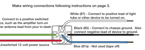
- Green (86): Connect to a positive switched power source (e.g., amplifier turn-on lead).
- Red (30): Connect to a constant (unswitched) 12V power source.
- White (87): Connect to the positive lead of the device to be turned on.
- Black (85): Connect to chassis ground.
- Blue (87a): Not used (tape off).
Application: Relay Turn-Off
Used to disable a device, such as a car starter system, when an alarm is triggered.
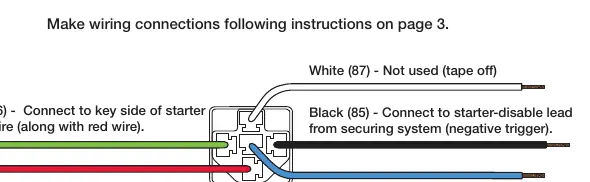
- Green (86): Connect to the key side of the starter trigger wire.
- Red (30): Connect to the key side of the starter trigger wire.
- Black (85): Connect to the starter-disable lead from the security system.
- Blue (87a): Connect to the solenoid side of the starter wire.
- White (87): Not used (tape off).
Application: Remote Trunk Release
Allows opening the trunk using a security system remote. Requires an existing power-assisted trunk release switch.
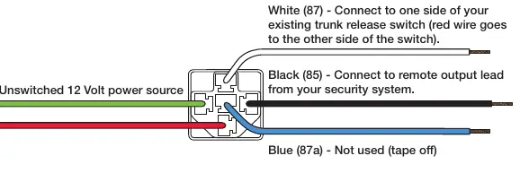
- Green (86): Connect to a constant (unswitched) 12V power source.
- White (87): Connect to one side of the existing trunk release switch.
- Black (85): Connect to the remote output lead from the security system.
- Blue (87a): Not used (tape off).
- Note: If the trunk switch only works when the key is on, connect the Red (30) wire to the unswitched 12V power source along with the Green (86) wire.
Application: Power Door Lock System
Requires an actuator for each door and two relays to activate aftermarket power door locks via a security system remote.
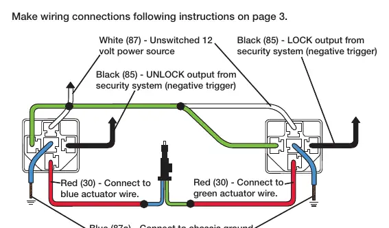
- Green (86) & White (87): Connect to a constant (unswitched) 12V power source.
- Black (85): Connect to the LOCK/UNLOCK output from the security system.
- Red (30): Connect to the actuator wires.
- Blue (87a): Connect to chassis ground.
Application: Antenna Turn-On
Specific to 1981-1995 Mazda vehicles with factory-equipped power antennas. This application switches a positive signal to a negative signal.
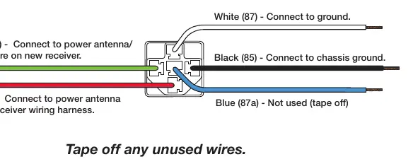
- Green (86): Connect to the power antenna/remote wire on the new receiver.
- Red (30): Connect to the power antenna wire on the receiver wiring harness.
- Black (85) & White (87): Connect to chassis ground.
- Blue (87a): Not used (tape off).
Practical help
Common problems
Trunk switch only works when the key is on
Connect the red (30) wire together with the green (86) wire to the unswitched 12V power source.
Unused wires causing potential shorts
Always tape off any unused wires.
Before use
- Compare items on your invoice with items received.
- Ensure you have a wire stripper/crimp tool.
- Have crimp caps available for connections.
- Identify the correct wiring diagram for your specific application.
- If running a wire to the battery, install a 30-amp fuse in-line.
Images and diagrams
- Wiring diagrams illustrate the specific pin connections required for different automotive functions.
- The dot symbol in diagrams indicates a wire splice.
Model compatibility
- Antenna Turn-On application is specific to 1981-1995 Mazda vehicles with factory-equipped power antennas.

Manual page author
Emily Carter
User documentation editor
Prepares concise manual descriptions and highlights the most useful setup, operation, and maintenance information for readers.