Tools / Hydraulic Tools
User Manual for Pittsburgh 1000LB Engine Stand 59201
Quick guide for the Pittsburgh 1000LB Engine Stand (Item 59201). Includes assembly steps, operating instructions for mounting and rotating engines, safety precautions, and maintenance tips.
Table of contents
Manual images
Click an image to enlargeImportant Information from the Manual
This manual provides essential safety, assembly, and operating instructions for the Pittsburgh 1000LB Engine Stand (Item 59201). Always read the full safety information before use. The stand is designed for a maximum capacity of 1,000 lb. Ensure the stand is placed on a flat, level, hard, and smooth surface before use.
Assembly Instructions
Follow these steps to assemble the engine stand:
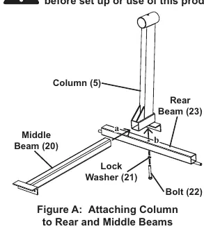
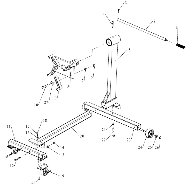
- Attaching Column to Beams: Insert the Middle Beam (20) into the receiver at the bottom of the Column (5). Place the Rear Beam (23) against the Column, align the holes, and secure with Bolt (22) and Lock Washer (21).
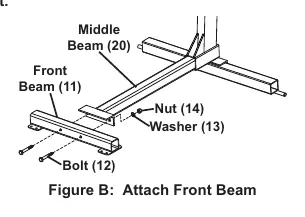
- Attaching Front Beam: Use Bolts (12), Washers (13), and Nuts (14) to attach the Front Beam (11) to the Middle Beam (20).
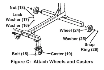
- Attaching Wheels and Casters: Attach Casters (19) to the Front Beam (11) using Bolts (15), Washers (16), Lock Washers (17), and Nuts (18). Slide a Wheel (24) onto each axle at the end of the Rear Beam (23), add a Washer (25), and secure with a Snap Ring (26).
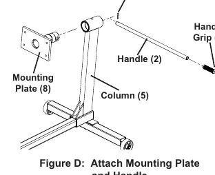
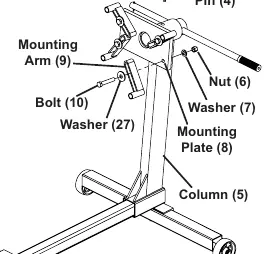
- Attaching Mounting Plate and Handle: Grease the Mounting Plate (8) shaft. Insert the shaft into the top of the Column (5). Insert the Handle (2) through the Mounting Plate (8) and secure with the Cotter Pin (3).
- Installing Arms: Attach the Mounting Arms (9) to the slots in the Mounting Plate (8) using Bolts (10), Washers (7), and Nuts (6).
Operating Instructions
Mounting an Engine:
- Position the stand on a flat, level surface and lock the swivel casters.
- Remove the Pin (4) from the Column (5).
- Use grade 8 bolts (not included) to attach the engine to the Mounting Plate (8). Ensure the bolt heads press against the back of the Arms; use flat washers as spacers if needed.
- Use all four Mounting Arms (9) when attaching an engine.
- Tighten the Bolts (10) and Nuts (6) that hold the Mounting Arms (9) to the Mounting Plate (8).
- Lower the engine crane until the stand supports the engine's weight, then release the engine from the crane.
- Rotate the engine to the desired angle and insert the Pin (4) into the top of the Column (5).
Rotating the Engine: While holding the Handle (2) and the engine to prevent accidental rotation, remove the Pin (4). Rotate the engine to the desired angle and re-insert the Pin (4).
Maintenance and Servicing
- Before Each Use: Inspect the stand for cracks, bends, or unusual wear. Check that all hardware is securely fastened and that casters turn properly.
- Cleaning: Keep the stand clean and free of dirt or grease. After use, clean external surfaces with a clean, moist cloth.
- Repairs: Do not use damaged equipment. If unsafe conditions are found, take the stand to a qualified technician for service.
Practical help
Common problems
Engine rotation is difficult or unstable
Ensure the Pin (4) is fully removed before rotating and that the stand is on a flat, level surface.
Parts are missing or damaged upon unpacking
Do not use the stand. Contact Harbor Freight Tools at 1-888-866-5797 immediately.
Unsure about bolt requirements for engine mounting
Use grade 8 bolts (not included) that are long enough to fit through the arms and thread deeply into the engine block.
Before use
- Inspect the stand for cracks, bends, or signs of unusual wear.
- Verify all hardware is securely fastened.
- Ensure casters are clean and turn properly.
- Confirm the engine weight does not exceed the 1,000 lb capacity.
- Ensure the assembly area is clean and well-lit.
- Lock the swivel casters before mounting an engine.
Specs in practice
- Weight Capacity
- 1,000 lb maximum load.
- Assembled Dimensions
- 35-1/2 in L x 29-1/2 in W x 34-3/8 in H.
Images and diagrams
- Figure A: Attaching Column to Rear and Middle Beams.
- Figure B: Attach Front Beam.
- Figure C: Attach Wheels and Casters.
- Figure D: Attach Mounting Plate and Handle.
- Figure E: Installing Arms and Locking Rotation.
Model compatibility
- Requires grade 8 bolts (not included) for engine mounting.
- Use all four mounting arms when attaching an engine to the stand.

Manual page author
David Miller
Documentation analyst
Organizes user manual content into clear summaries, with attention to model details, product context, and everyday usability.