Electronics / Networking
QSFPTEK Mux Demux & OADM User Manual
Quick start guide for QSFPTEK Mux Demux & OADM. Includes installation instructions for FMU modules and 1U rack mounts, port configuration, and safety requirements.
Table of contents
Manual images
Click an image to enlargeQuick guide from the manual
This guide provides instructions for the QSFPTEK Mux Demux & OADM series, available in FMU Plug-in Module and 1U Rack formats. It covers installation, port configuration, and safety requirements for integrating these devices into your network.
Accessories
Ensure the following items are included before starting installation:
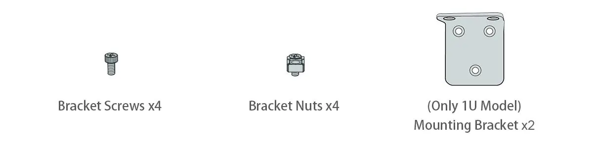
- Bracket Screws (x4)
- Bracket Nuts (x4)
- Mounting Brackets (x2, for 1U models only)
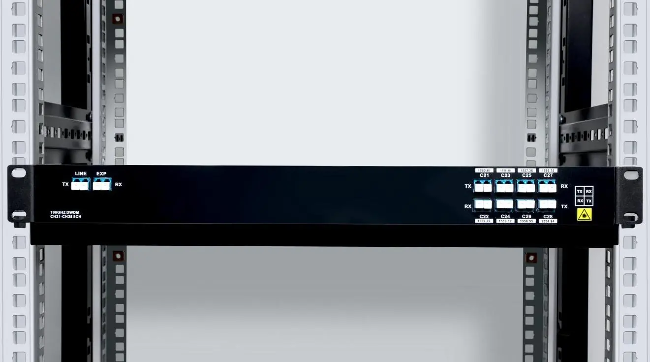
Functional Ports Overview
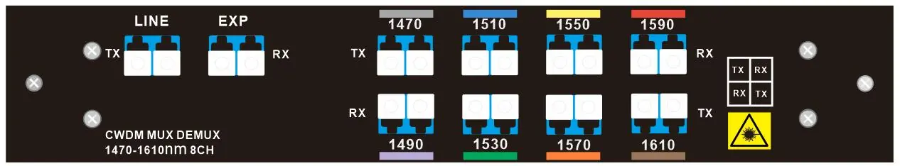
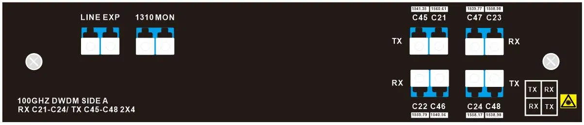
The devices feature specific port configurations for signal management:
- RX/TX Ports: Used for channel wavelength transmission and reception.
- EXP Port: Used for connecting to other Mux devices for capacity enhancement.
- 1310nm Port: Dedicated port for capacity enhancement.
- Monitor Port: Extracts 1% of the signal for monitoring channel power levels.
Installation Requirements
Before installation, ensure you have the necessary tools and environment:
- Tools: Screwdriver, static-proof wristband, and bolts.
- Safety: Keep the area clean and dust-free. Wear protective glasses if necessary. Use tight clothing and roll up sleeves to avoid snagging.
- Environment: Ensure the workshop is well-ventilated to allow heat discharge. Follow electrostatic discharge (ESD) prevention procedures. Ensure the machine box is sealed and placed where cool air can circulate.
Installation
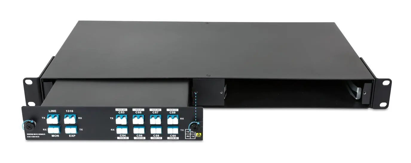
FMU Plug-in Module
- Position the module to match the chassis shelf.
- Insert the module into the shelf space carefully.
- Apply pressure to engage the M3 captive screws, then tighten them on both sides.
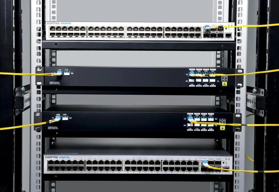
Mounting the Chassis in a Rack
- Install the mounting brackets on the left and right sides of the chassis.
- Carefully install the chassis into the rack.
- Secure the chassis using M6x12mm screws and M6 nuts.
Connecting Fiber Cable
Connect the fiber cables to the appropriate RX/TX ports as indicated by the device labeling. Ensure all connections are secure and follow standard fiber handling procedures to avoid signal loss or damage.
Support and Product Warranty
QSFPTEK provides a 3-year limited warranty for Mux Demux & OADM products. For technical support, contact the team via email at [email protected] or visit the official website for live chat and additional resources.
Manufacturer information
QSFPTEK
Practical help
Common problems
Overheating
Ensure the workshop is well-ventilated and the machine box is placed where cool air can blow off heat.
Electrostatic damage
Always follow electrostatic discharge (ESD) prevention procedures and wear a static-proof wristband during installation.
Before use
- Verify all accessories (screws, nuts, brackets) are present.
- Ensure a screwdriver and static-proof wristband are available.
- Confirm the installation site is clean and dust-free.
- Check that the rack or chassis is properly ventilated.
- Verify the specific Mux/Demux channel configuration required for your network.
Specs in practice
- Monitor Port
- Extracts 1% of the signal, allowing for non-intrusive monitoring of channel power levels.
Images and diagrams
- Port layout diagrams illustrate the specific RX/TX channel assignments for different models (CWDM/DWDM).
- Installation diagrams show the correct orientation for inserting FMU modules into the 2-slot chassis.
- Rack mount diagrams demonstrate the attachment of brackets to the chassis before installation.
Model compatibility
- Products are available in FMU Plug-in Module and 1U Rack formats.
- Ensure the chassis type matches the module format (FMU vs 1U).

Manual page author
David Miller
Documentation analyst
Organizes user manual content into clear summaries, with attention to model details, product context, and everyday usability.